| Line 416: | Line 416: | ||
. | . | ||
===== MF_FixtureUVs ===== | ===== MF_FixtureUVs ===== | ||
[[File:MatFunction FixtureUVs.jpg|thumb]] | |||
This node is the bread-and-butter of custom paint and fixture materials. It contains all the logic and maths required for applying a texture to a model, and should be used in 99% of situations where you want to apply a texture to your Custom Paint shader. | This node is the bread-and-butter of custom paint and fixture materials. It contains all the logic and maths required for applying a texture to a model, and should be used in 99% of situations where you want to apply a texture to your Custom Paint shader. | ||
| Line 430: | Line 431: | ||
* World Position - Leave this section blank, unless you wish to override the world position used to calculate the current pixel's location in world-space. In 99% of situations, this is left blank. | * World Position - Leave this section blank, unless you wish to override the world position used to calculate the current pixel's location in world-space. In 99% of situations, this is left blank. | ||
* Cutoff Offset - Leave this section blank, unless you wish to override the ratio at which a texture switches between the cardinal directions used for the box unwrap. in 99% of situations, this is left blank. | * Cutoff Offset - Leave this section blank, unless you wish to override the ratio at which a texture switches between the cardinal directions used for the box unwrap. in 99% of situations, this is left blank. | ||
* Texture Offset - This input defaults to using two <code>editable_</code> parameters for adjusting the texture offset | * Texture Offset - This input defaults to using two <code>editable_</code> parameters for adjusting the texture offset. If left blank, two sliders will appear in-game for adjusting the X and Y axis of the texture. Override this only if you know what you are doing. | ||
* Texture Rotation - | * Texture Rotation - This input, unlike the Texture Offset input, does not have a default parameter attached to it. This is because it is unfortunately not possible, currently, to rotate the UVs of an exported material. As such, this input remains unused. You can override it to adjust the rotation of the textures along each of the three cardinal directions, as each component of the vector represents a fraction of rotation (ie: a vector [x,y,z] is really just a combination of three rotations, as 0-1 being a 0-360 degree rotation. so a vector [0.25,0.5,1] would rotate the X axis by 90 degrees, the Y axis by 180, and the z axis by 0 degrees). | ||
* Output Vec4 - | * Output Vec4 - This bool is False by default. If the texture you are using contains RGBA information, and you are using the Alpha channel in your material, set this bool to True, otherwise leave blank. | ||
* Use Mesh UVs - | * Use Mesh UVs - This bool is False by default. If enabled, most of the features of this node are disabled and only the Texture Size input is used, as a multiplier on the UVs. | ||
* Has Texture Transition - | * Has Texture Transition - This bool is False by default. If enabled, the box unwrap tries to do a blended transition between each of the three unwraps. This is useful for fine-detail or stochastic, noisy, textures. If left as False, it uses a hard cutoff where the transition between the three unwraps is more obvious. This is useful for textures that try to imitate real patterns, as the hard seams imitate actual seams between sheets of material. | ||
Outputs; | Outputs; | ||
* Result - | * Result - This is the unwrapped texture, as either a Vec3, or Vec4 (If Output Vec4 is set to True). If no Texture Object is supplied, this output is unused. | ||
* Normal - | * Normal - This is as above, but for normal maps. If your texture is a normal map, use this output paired with the Normal Object input. If no Normal Object is supplied, this output is unused. | ||
* UVs - | * UVs - This is the resulting UVs used for the Texture and Normal Object texture samplers. If you need to use the UVs for more than one texture, or a texture that is not a Colour or Normal Map, this output combined with the DDX and DDY outputs can be used on a texture sampler to get the same result. | ||
* DDX - | * DDX - Because the UVs of this node are generated procedurally, the DDX and DDY of the UVs need to be explicitly defined and fed to the Texture Sampler. If you are using your own texture sampler, you need to use the DDX and DDY outputs as well as the UVs. You cannot use the UVs just on their own. | ||
* DDY - | * DDY - See above. | ||
===== MF_NormalStrength ===== | ===== MF_NormalStrength ===== | ||
[[File:MatFunction NormalStrength.jpg|thumb]] | |||
This node will adjust the strength of a normal map. This is useful when a normal map does not perfectly represent the material you wish to create, or when the material is dynamic and adjustment of the normal map is desired. | |||
It has two inputs; | |||
* Normal - This is the normal vector you want to adjust. | |||
* Strength - This is a scalar value that will effectively multiply the normals. A strength of 1 means the normal map is un-affected, a strength of 2 means the normal map is twice as strong, a value of 0 will mean the normal vector has no effect on the surface normals of the material, and a value of -1 will invert the direction of the X and Y components of the normal (effectively inverting the normal map without inverting the direction of the surface polygon) | |||
Revision as of 20:17, 5 January 2023
Beginning with LCv4.2, Automation supports the creation of custom paint materials which can be applied to cars, fixtures, and engine parts. These materials also support the Exporter, including exporting to BeamNG.
Overview
A Custom Paint mod is a collection of files, of which a Custom Paint file is the parent.
The Custom Paint file contains the settings and applicable options for the Custom Paint, as well as a reference to the paint material.
The custom paint material itself is a Material in UE4, which is set up in a specific way. Material variables can have an editable_ prefix in their name if you want the player to have access to it in the custom paint settings in-game. Variables and parameters also need to be input into the export user data, contained within the material, for them to export correctly. Materials will not export correctly at all without this export user data.
Workflow
- In UE4:
- Set up a mod.
- Create and fill out a
Custom Paintfile. - Create your Custom Paint material.
- Assign variables to the export user data.
- In the Automation Workshop Publishing Tool:
- Set up a workshop item.
- Share your mod.
Create your Custom Paint mod
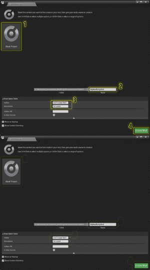
Create A New Mod
After setting up the modding SDK from Here, create a new blank mod:
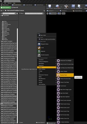
Create A Custom Paint File
In your mod content folder, right-click and add a new Custom Paint file. This is the file the game uses to load the paint into the UI.
Open the Custom Paint file. It has a few parameters:
- Name - This will be the name of the paint as it will appear in-game.
- Material Instance - This is the actual paint itself. The material instance defines how the paint looks, what parameters are available, and how it looks when exported.
- GUID - This is an unique identifier for this custom paint. It is a random value. This is how the paint is stored and saved by the game.
- Family GUID - As above, this is an unique identifier. This one is currently un-used, but could in the future be used for storing what paints are part of the same family, if you decide to make several.
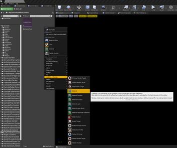
Create A Material
Right-click the content browser again, and create a new Material. This is the actual shader: it defines how the paint looks.
Open the material. UE4 uses standard PBR Metallic-Roughness workflows. What this means is you define a material by giving it:
- a colour (0,0,0 - 1,1,1)
- telling it how rough it is (0 - 1, 0 being shiny)
- how metallic it is (0 - 1, 0 being plastic)
as well as a few additional things that help optimise parts of the rendering process, such as:
- a Normal map (this defines surface detail that would be too fine or complicated to be geometry)
- an Ambient Occlusion map (this helps darken and reduce reflections and specular highlighting on parts of the geometry that should be darker than usual, and which the lighting model cannot properly calculate)
- Opacity/Opacity Mask
- etc..
Material Requirements
Opacity
All Custom Paint materials must be set to Masked, unless it is a transparent material.
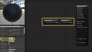
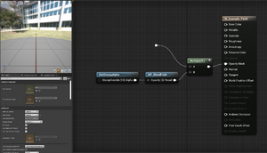
Two nodes should be a part of the Opacity or Opacity Mask input. If your material does not have any transparent or masked info, these two nodes are still required.
If your material does have opacity information, simply add these two nodes at the end with a multiply:
Two-Sided Material
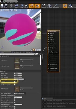
If at all possible, your material should be set to two-sided. This ensures the interior of the car doesn't have any transparency holes in it from fixtures or paints. To enable Two-Sided, click on the main material node in the material editor, and in the details panel, under the Material category, Tick Two Sided.
Parameter Names
For parameters to appear in-game in the UI for the player to customize, it must have the editable_ prefix. Only Vector and Scalar parameters will appear in the UI. Vector parameters will always appear as a Colour Picker, and Scalar parameters will mostly always appear as a Slider. If a Scalar parameter also has the _Bool suffix, it will instead appear as an Enable/Disable switch. A Vector parameter cannot have the _Bool suffix.
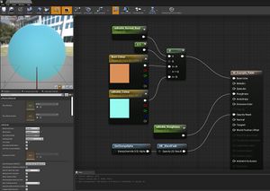
Example parameters:
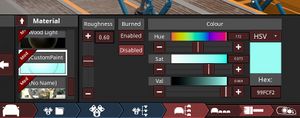
Note how in-game the Burn Colour parameter isn't visible, and the Burned parameter is an Enable/Disable toggle. This is because the Burn Colour parameter did not have the editable_ prefix, and the Burned parameter had the _Bool suffix. Also note how the Scalar parameter appears as a slider, and the Vector parameter appears as a colour picker.
Export Material User Data
Export Material User Data main page
From the details panel of the material, expand the Material category, and from the Asset User Data array, add an Export Material User Data. This is where the values and parameters for the material are stored for the exporter. The exporter can only see the parameter names in the export user data. The exporter cannot know the layout of the parameters in the material, and cannot, therefore, know how to use those parameters. The export user data exists to simplify the parameters down to a known layout, such that the exporter can then line those values up with what the BeamNG material system uses, as well as other potential exporter plugins.
Note that the export user data only has access to a limited subset of behaviors for materials, and cannot do a lot of the fancy things that the UE4 material editor is capable of. It should, however, still be sufficient for most basic and intermediate-level materials.
Once you have fed your parameters into the export user data, your material should now export correctly.
Helper Functions For Materials
Inside materials and from the palette menu, or the right-click menu, you can access custom material functions that have been made and exposed to the material system. These nodes are designed to help you with designing your materials. Camso has designed a few material functions that help with designing custom paint materials. These materials can be accessed from the Camso or Custom Paint sub-categories within the palette or right-click menu inside materials.
The following nodes and material functions will help you to make materials easier:
GetStampAlpha
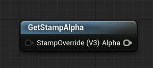
This is one of the most important nodes, as it deals with all the functions, variables, and textures, that are used by the game to put the stamp holes on cars and fixtures. Without this node, fixture stamping does not work. Your material must be set to masked, and this node must be plugged into the opacity mask section.
It has one input, and you should not do anything with it.
MF_AASmoothStep
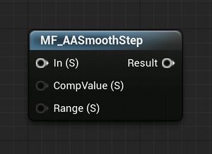
This is useful for turning a range of values into a 0 or a 1, or turning a range of values into a step where black suddenly turns to white.
It has three inputs;
- In - this is the value you want to turn into a 1 or a 0
- CompValue - If the In value is above this, the out value will be 1. if In is less than this value, the output will be 0.
- Range - This is how large of a transition period the value should change in, in screen-space pixels. A small value will change over the course of a single pixel or less, and a large value will change over many pixels.
MF_BlendAngleCorrectedNormals
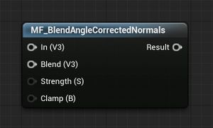
This blends multiple normal maps together, with correctly normalized results. Other methods of blending normal maps do not correctly account for the blue vector, or do not accurately derive the blue vector. This method is more compute-intensive, but results in perfectly-blended normals.
It has four inputs;
- In - this is the base normal, which you want to blend another normal with
- Blend - this is the second normal that you want to add to the first
- Strength - This is how much of the Blend normal you want to add to the base normal
- Clamp - this ensures that none of the normal
MF_BlendFade
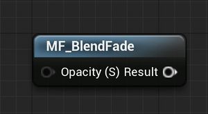
This is a mandatory node as part of the material for custom paints or fixture materials. Multiply it with any other part of your opacity mask network, or if you dont have any, plug it right in.
it has one input;
- Opacity - This lets you pass in any other opacity value, and it will be blended with this node. this is mostly used to plug in the GetStampAlpha material function.
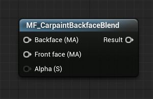
MF_CarpaintBackfaceBlend
This node will take two material attributes, and let one pass through for the front faces, and the other through for the backfaces.
It has three inputs;
- Backface- This takes a Material Attributes in, and will pass it through to the output only if the current pixel is of the backface of a polygon.
- Front face- This takes a Material Attributes in, and will pass it through to the output only if the current pixel is of the front face of a polygon.
- Alpha - This is an optional input, and will override the default mask used to detect whether a face is the front or back of a polygon.
MF_DynamicGrungeAndWear_Mask
This node will create a mask ( a 0-1 value) where 1 will appear on corners and sharp curves, and 0 will appear on flat surfaces.
it has six inputs;
- Curvature Cutoff - This will adjust how small/thick the corners will be, where a larger value will make the grunge mask thicker on corners.
- Dirtiness - This is the only mandatory input. It takes a scalar value between 0 and 1, where 0 will be no grunge output, and 1 will be the most grunge.
- Adjust A Power - this node will adjust some of the grunge mask generation.
- Adjust A Divide - this node will adjust some of the grunge mask generation.
- Adjust B Power - this node will adjust some of the grunge mask generation.
- Adjust B Divide - this node will adjust some of the grunge mask generation.
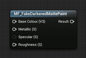
MF_FakeDarkenedMattePaint
This node is useful when making paint, as it forces the specular channel darker as the paint colour becomes darker.
Because UE4 uses a fast PBR workflow, even a pure black non-metallic surface will appear somewhat bright, so this node is useful for darkening the paint further by dynamically adjusting the specular channel of the material.
This material is used by plugging the Base Colour, Metallic, (optional) Specular, and Roughness inputs from your material into this node, and plugging the output into the Specular channel of the material.
It has four inputs;
- Base Colour - Plug the material's base colour input into here.
- Metallic - Plug the material's Metallic input into here.
- Specular - Plug the material's Specular input into here, if it is used. If not, leave empty.
- Roughness - Plug the material's Roughness input into here.
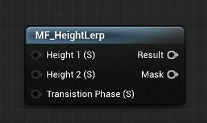
MF_HeightLerp
This node creates a more useful blend between two heightmaps than a simple Lerp or SmoothStep function. It takes two heightmaps, one for each of the materials or textures that you wish to blend, as well as a Transition Phase (or Alpha), and outputs a new heightmap and mask for use in a Lerp or other material blend function.
The result of this node is a mask for blending between two textures or materials, modulated by the heightmaps of those textures or materials. This is useful for blending, say, bricks into grass, as it will account for the height of each brick, and blend the grass first into the cracks and mortar.
It has three inputs;
- Height 1 - This is the heightmap of the first texture/material you wish to blend.
- Height 2 - This is the heightmap of the second texture/material you wish to blend.
- Transition Phase - This is the phase of the transition, otherwise known as an alpha, for blending between Height 1 and Height 2. A transition phase of 0 means the mask will let all of Height 1 through, and a value of 1 will let as much of Height 2 through as it can, given the height values of each input. a Value of 0.5 will blend the two heights equally.
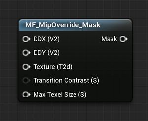
MF_MipOverride_Mask
This is a fun one. It acts a bit like a Camera Depth Fade, where it defines a transition mask based on depth or distance, but instead of using distance from pixel to camera, which is prone to inconsistencies with different FOVs, it instead uses the distance between the UVs of the adjacent pixels to define its mask. What this means is, regardless of the distance from the camera, or the FOV, the mask output from this node will always occur at the same texel density.
This node was developed for the Fixture Taillight Glass material, where if the glass was small enough on screen, the pixels between the textures was creating enough noise that a transition to a simplified version of the material was needed. Since the material can change scale based on the fixture's size, the camera can move farther or closer away from the car depending on the camera's position, and the FOV can change depending on the user's game or photoscene settings, this was the only way to consistently define a mask for the simplified version of the material.
It will output a 1 if the current pixel's texel size is less than the input threshold.
It has five inputs;
- DDX - This is the DDX of the UVs for the texture.
- DDY - This is the DDY of the UVs for the texture.
- Texture - This is the texture object of the texture you wish to override at a certain texel size.
- Transition Contrast - This is how much of a range you wish the mask to blend between. A lower value means a sharper, more immediate blend.
- Max Texel Size - This is the minimum size of a texel, in horizontal or vertical screen pixels, that you wish the texture to be visible. If the texture is smaller than this value, the mask output is 1.
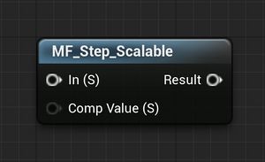
MF_StepScaleable
This is a more performant version of MF_AAStep, where at lower shader settings, it falls back to a standard Step function.
It has two inputs;
- In - This is the value you want to apply the Step function to.
- Comp Value - This is the value at which you want the input to return 1. If the input value is less than the comp value, the result will be 0.
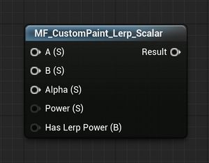
MF_CustomPaint_Lerp_Scalar
This node follows the logic of the export parameters, where the values A and B can be LERP-ed together by an Alpha, and an optional Power. The power node forces the Alpha downward, such that the LERP becomes more exponential. A higher value of Power results in the Alpha applying a smoother blend between A and B. The Power is blended into the Alpha such that the higher the alpha, the less the power is applied. the end result is more control over the lower values of Alpha, while the higher values remain closer to a linear blend.
This node is useful for a Scale input for textures, as the Alpha can be driven by a player-editable parameter (with the editable_ prefix) and the player has more control over the scale of the texture at lower scales.
The formula for the output is as such:
lerp (A, B, Lerp(Power, Alpha, Power))
It has five inputs;
- A - Just like a lerp, this is the A input. If the Alpha is 0, the result is 100% A.
- B - Just like a lerp, this is the B input. If that Alpha is 1, the result is 100% B.
- Alpha - Just like a lerp, this is the Alpha input. If the Alpha is 0, the result is 100% A, if Alpha is 0.5, the result is equally half of A and B (unless the Power input is anything other than 1, and the Has Lerp Power is True.)
- Power - This is the modifier for Alpha. A value above 1 will slowly force the lower values of Alpha further down towards 0, much like a power node would, but higher values of Alpha will remain higher. This is done by applying a second Lerp between the Power and Alpha inputs.
- Has Lerp Power - This a bool input. If the input bool is True, the Power input is evaluated. If False, the Power input is ignored and this node acts exactly like a standard lerp.
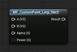
MF_CustomPaint_Lerp_Vec2
Exactly like the scalar version of this node, except it works on Vec2 values instead of scalars.
.
.
.
.
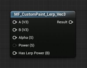
MF_CustomPaint_Lerp_Vec3
Exactly like the scalar version of this node, except it works on Vec3 values instead of scalars.
.
.
.
.
.
MF_CustomPaint_Lerp_Vec4
Exactly like the scalar version of this node, except it works on Vec4 values instead of scalars.
.
.
.
.
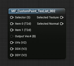
MF_CustomPaint_TexList_002
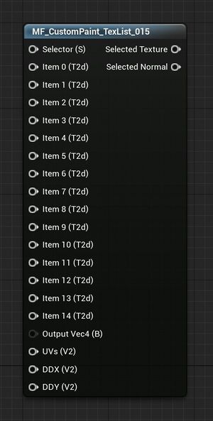
This node, like the similarly-named nodes that follow, are part of a set of nodes that may help you set up logic for allowing the player to change the texture of a material with a slider.
Because the current Custom Paint system doesnt allow for a texture-selector interface of any kind, one must be hacked together using some other method. This node uses a slider.
MF_CustomPaint_TexList_002 allows you to set up two textures for the player to switch between, by feeding an editable_[Scalar] parameter into the Selector input, and a texture object parameter into each of the Item0/1 inputs.
it has seven inputs;
- Selector - This is where you would feed your
editable_scalar parameter. The parameter moves between 0 and 1, where each step corresponds to a texture from the Item list of inputs. - Item 0 - This is the first texture to be selected from the list, as a Texture Object Parameter. Because this list only contains two items, it will be present so long as the Selector input is between 0 and 0.5.
- Item 1 - This is the second texture to be selected from the list, as a Texture Object Parameter. Because this list only contains two items, it will be present so long as the Selector input is between 0.5 and 1.
- Output Vec4 - If the texture you are using this node for contains RGBA info, and you are using the Alpha channel in your material, set this bool to True, otherwise leave it.
- UVs - This is the UVs of your texture. This node handles the texture sampling of your texture, so it needs the UVs to be passed through.
- DDX - Because the UVs of many of Automation's textures are handled dynamically, the DDX and DDY of the UVs are often needed. As such, they are required here. This incurs no additional cost to the shader engine, as the internal texture sampler calculates them also. If you do not have or require the DDX and DDY of your UVs, simply drag out of the UVs node that you fed into the above input, and get the DDX.
- DDY - As above, feed the DDY of the UVs into here.
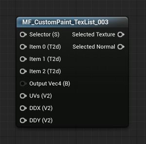
MF_CustomPaint_TexList_003
Exactly like the two-texture list version of this node, except it selects between three textures.
.
.
.
.
.
.
.
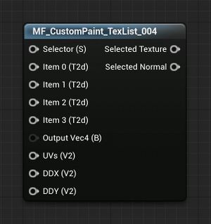
MF_CustomPaint_TexList_004
Exactly like the two-texture list version of this node, except it selects between four textures.
.
.
.
.
.
.
.
.
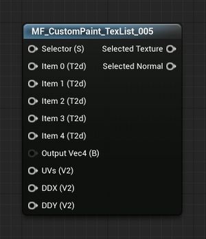
MF_CustomPaint_TexList_005
Exactly like the two-texture list version of this node, except it selects between five textures.
.
.
.
.
.
.
.
.
.
MF_CustomPaint_TexList_006
Exactly like the two-texture list version of this node, except it selects between six textures.
MF_CustomPaint_TexList_007
Exactly like the two-texture list version of this node, except it selects between seven textures.
MF_CustomPaint_TexList_008
Exactly like the two-texture list version of this node, except it selects between eight textures.
MF_CustomPaint_TexList_009
Exactly like the two-texture list version of this node, except it selects between nine textures.
MF_CustomPaint_TexList_010
Exactly like the two-texture list version of this node, except it selects between ten textures.
MF_CustomPaint_TexList_011
Exactly like the two-texture list version of this node, except it selects between eleven textures.
MF_CustomPaint_TexList_012
Exactly like the two-texture list version of this node, except it selects between twelve textures.
MF_CustomPaint_TexList_013
Exactly like the two-texture list version of this node, except it selects between thirteen textures.
MF_CustomPaint_TexList_014
Exactly like the two-texture list version of this node, except it selects between fourteen textures.
MF_CustomPaint_TexList_015
Exactly like the two-texture list version of this node, except it selects between fifteen textures.
.
.
.
.
.
.
.
.
.
.
.
.
.
.
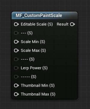
MF_CustomPaintScale
This is a more advanced version of the Custom Paint Lerp Scalar node, specialized more for use as a scale modifier for UVs. It has separate scale inputs for the texture itself, and the thumbnail version of the custom paint. This allows the scale to be set differently for the thumbnail of the custom paint, as the thumbnail mesh is a 2cm^2 mesh and most scales of a texture would look poor at this size.
It has six inputs (the greyed-out inputs that are just dashes (--) are there solely as separators for organization);
- Editable Scale - This is where you would feed your editable_ scalar parameter for adjusting the scale in-game
- Scale Min - The minimum scale you wish the slider to be.
- Scale Max - The maximum scale you wish the slider to be.
- Lerp Power - Just like the Custom Paint Lerp Scalar node, this is the power adjust for the scale.
- Thumbnail Min - Just like Scale Min, this is the minimum scale you wish the slider to be, but this only affects the thumbnail of the material in-game.
- Thumbnail Max - Just like Scale Max, this is the maximum scale you wish the slider to be, but this only affects the thumbnail of the material in-game.
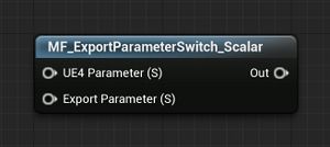
MF_ExportParameterSwitch_Scalar
Sometimes, you want a different value to be used for the export of the material than the one that is used inside Automation. This node exploits a feature of the UE4 engine that allows parameters to exist without affecting the performance or appearance of the shader in-game. In this way, you can feed a parameter to the exporter that has no bearing on the in-game material.
It has two inputs;
- UE4 Parameter - This is the parameter that you wish to use for the material. it can also be used for the exporter.
- Export Parameter - This is the parameter input that you wish to use for the exporter. This has no effect on the material.
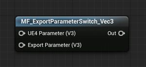
MF_ExportParameterSwitch_Vec3
Exactly like the scalar version of this node, except it works on Vec3 values instead of scalars.
.
.
.
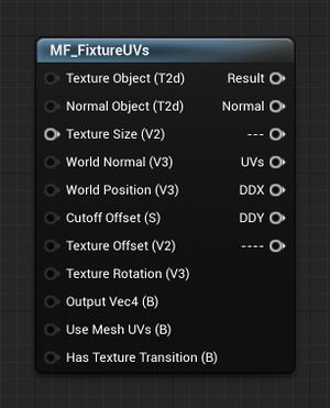
MF_FixtureUVs
This node is the bread-and-butter of custom paint and fixture materials. It contains all the logic and maths required for applying a texture to a model, and should be used in 99% of situations where you want to apply a texture to your Custom Paint shader.
By default, it applies a World-Aligned box-projected texture map, except centered on the car instead of the world origin. What this means is, all textures are relative to the car. As the car moves, the textures remain the same, but if a fixture with this material applied to it moves, the texture will appear to 'crawl', as the textures remain aligned to the car while the fixture is moving. This is useful when the player wants to use many fixtures with the same custom paint applied to it, as the textures in those custom paints will align and appear as a single texture. By aligning it to the car instead of the world, it also mitigates the issue where textures would crawl and appear mis-aligned if the car is moved or rotated in the photoscene.
It has many inputs and outputs;
Inputs;
- Texture Object - Input the texture object parameter you wish to use here. Unless it is a normal map, in which case use the Normal Object input.
- Normal Object - If the texture object you wish to use is a normal map, use this input instead.
- Texture Size - Input a scalar value here, in world units (a value of 1 is equal to 1cm, and a value of 100 is equal to 100cm), and your texture will be mapped at this scale.
- World Normal - Leave this section blank, unless you wish to override the world normal used to calculate the current pixel's normal vector in world-space. In 99% of situations, this is left blank.
- World Position - Leave this section blank, unless you wish to override the world position used to calculate the current pixel's location in world-space. In 99% of situations, this is left blank.
- Cutoff Offset - Leave this section blank, unless you wish to override the ratio at which a texture switches between the cardinal directions used for the box unwrap. in 99% of situations, this is left blank.
- Texture Offset - This input defaults to using two
editable_parameters for adjusting the texture offset. If left blank, two sliders will appear in-game for adjusting the X and Y axis of the texture. Override this only if you know what you are doing. - Texture Rotation - This input, unlike the Texture Offset input, does not have a default parameter attached to it. This is because it is unfortunately not possible, currently, to rotate the UVs of an exported material. As such, this input remains unused. You can override it to adjust the rotation of the textures along each of the three cardinal directions, as each component of the vector represents a fraction of rotation (ie: a vector [x,y,z] is really just a combination of three rotations, as 0-1 being a 0-360 degree rotation. so a vector [0.25,0.5,1] would rotate the X axis by 90 degrees, the Y axis by 180, and the z axis by 0 degrees).
- Output Vec4 - This bool is False by default. If the texture you are using contains RGBA information, and you are using the Alpha channel in your material, set this bool to True, otherwise leave blank.
- Use Mesh UVs - This bool is False by default. If enabled, most of the features of this node are disabled and only the Texture Size input is used, as a multiplier on the UVs.
- Has Texture Transition - This bool is False by default. If enabled, the box unwrap tries to do a blended transition between each of the three unwraps. This is useful for fine-detail or stochastic, noisy, textures. If left as False, it uses a hard cutoff where the transition between the three unwraps is more obvious. This is useful for textures that try to imitate real patterns, as the hard seams imitate actual seams between sheets of material.
Outputs;
- Result - This is the unwrapped texture, as either a Vec3, or Vec4 (If Output Vec4 is set to True). If no Texture Object is supplied, this output is unused.
- Normal - This is as above, but for normal maps. If your texture is a normal map, use this output paired with the Normal Object input. If no Normal Object is supplied, this output is unused.
- UVs - This is the resulting UVs used for the Texture and Normal Object texture samplers. If you need to use the UVs for more than one texture, or a texture that is not a Colour or Normal Map, this output combined with the DDX and DDY outputs can be used on a texture sampler to get the same result.
- DDX - Because the UVs of this node are generated procedurally, the DDX and DDY of the UVs need to be explicitly defined and fed to the Texture Sampler. If you are using your own texture sampler, you need to use the DDX and DDY outputs as well as the UVs. You cannot use the UVs just on their own.
- DDY - See above.
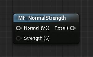
MF_NormalStrength
This node will adjust the strength of a normal map. This is useful when a normal map does not perfectly represent the material you wish to create, or when the material is dynamic and adjustment of the normal map is desired.
It has two inputs;
- Normal - This is the normal vector you want to adjust.
- Strength - This is a scalar value that will effectively multiply the normals. A strength of 1 means the normal map is un-affected, a strength of 2 means the normal map is twice as strong, a value of 0 will mean the normal vector has no effect on the surface normals of the material, and a value of -1 will invert the direction of the X and Y components of the normal (effectively inverting the normal map without inverting the direction of the surface polygon)
