Introduction
In Automation, designing an engine is a very in-depth process. There are hundreds of possible combinations of cylinder counts, layouts, head types, internal types, fuel system types, aspiration methods, and exhaust systems, with more to potentially come in the future. As of now, only 4-stroke gasoline engines can be built in the game.
How an Engine Operates

In order to understand how to design an engine, you must first know what an engine does, and how it works. The goal of an engine is to convert chemical energy of the fuel into rotational kinetic energy. This can be done by a variety of means, but in Automation, all engines operate on the Otto cycle, the 4-stroke engine cycle used by most gasoline (petrol) powered cars. This cycle works in four up-and-down cylinder motions (known as strokes). The first stroke, known as the intake or aspiration stroke, draws in air and fuel as the piston moves from top dead center to bottom dead center. The second stroke, known as the compression stroke, compresses the air and fuel mixture as the piston moves up towards top dead center. The third stroke, known as the ignition or combustion stroke, ignites the air and fuel mixture, causing combustion. The combustion forces the piston back down to bottom dead center. The fourth stroke, known as the exhaust stroke, evacuates the resulting exhaust gases by having the piston move up to top dead center, pushing out the gases. Once the exhaust is evacuated, the cycle starts over at the aspiration stroke. While the Otto 4-stroke cycle is not the only cycle in the real world, where other cycles exist such as the Atkinson 4-stroke cycle, or 2-stroke cycles, in Automation, the Otto cycle is the only cycle you need to know about.
ㅤ
Building an Engine - Engine Family Designer

In order to begin building engines, you will need to create an engine family. The engine family is the base of your subsequent engine variant(s). It covers the engine's cylinder count and layout, the materials out of which the engine is built, the minimum and maximum displacement (internal capacity) of the engine, and the valvetrain design. It is best to have the engine's purpose in mind before commiting to any choices. You wouldn't want to install a large-displacement 12-cylinder motor in an economy car, nor would you want to install a small 3-cylinder motor in a heavy duty truck... although both are possible with some finagling and creativity.

If you're building your engine to install it into a car trim, keep the engine dimensions in mind! Cars in Automation come in a magnitude of different sizes, some small, and some enormous. Likewise, the engine bay sizes also depend from car to car, depending on the car's size, and the way the engine is installed in the car. The size of the engine can affect the fitment in the engine bay, which can impact available drivetrain types and weight balance. The example car (upon which the example engine will be mounted in) has a longitudinal front engine mounting, giving it access to FWD, RWD, AWD and 4x4. However, due to the design of these drivetrains, the example engine might not be compatible with some of these drive types simply due to its size. The engine size menu is located on the bottom right of the designer, hidden (unless you press on the upward arrow). You will also see size arrows on the engine itself, which shows how close the engine is to being too large. How much area the engine takes up in the engine bay will affect engineering time and maintenance costs of the car. A fuller engine bay is harder to design, and harder to work on.
Engine Block
The engine block is the core of the engine. How you design your block will heavily affect your engine's purpose and how expensive, complex, heavy your engine may be. As of now, the game contains twelve engine block layouts and one DLC engine block layout. In general, more cylinders will increase the engine block's complexity, as well as using an engine layout with two cylinder banks (such as in a V or Boxer engine) as opposed to a single cylinder bank (as seen in an Inline engine).
Inline Engines
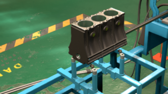
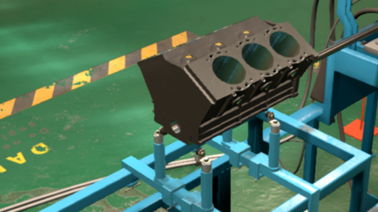
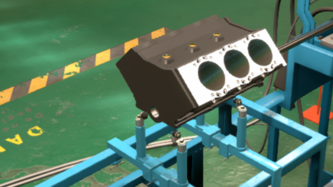
Inline-3

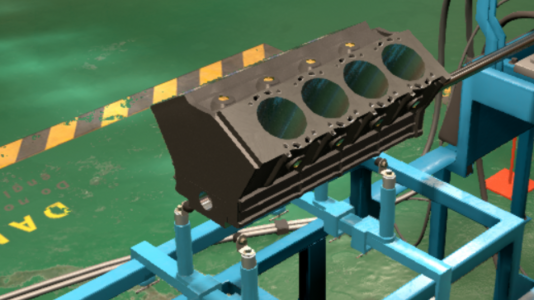
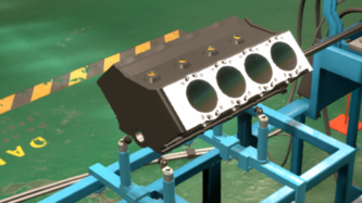
Inline-4
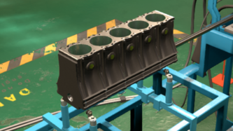
Inline-5
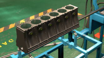
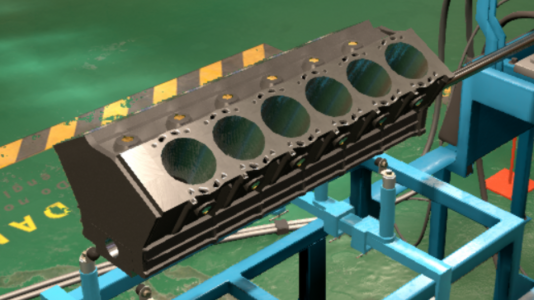
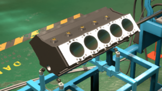
Inline-6


Inline engines are the simplest and most common engine layout, due to their use of a single head for their one cylinder bank. The inline engine's advantage, aside from simplicity, is their narrow dimensions, as all the cylinders are in a row. Their disadvantage lies in the fact that they can be quite long. A long engine may have a hard time fitting in a car's engine bay, depending on the layout of the engine bay. The longer the engine is, the more fragile it becomes, as the forces within the engine can cause the engine block and internal components such as crankshafts and camshafts to flex. This of course wont result in immediate failure, rather it causes stress over time.
- Inline-3 [I3] - The inline 3 is the cheapest engine layout in game, thanks to the use of only 3 cylinders, and a very compact block. The main appeal of an inline 3 engine block is its absolute cheapness. Its other advantage is high efficiency. Due to its simple construction, there is less internal friction in a 3-cylinder motor compared to any other design, improving its efficiency. The inline 3's disadvanatages are numerous. For one, due to the low cylinder count and assymetry, this layout has the lowest smoothness rating in game. This engine layout is also unfavorable towards performance applications, due to the usually small displacements of such engines. As a result, the inline 3 engine is best suited for small, budget-friendly, economical cars. In the game, this engine layout is available from the beginning.
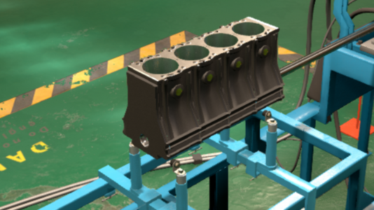
- Inline-4 [I4] - The inline 4 engine is the most ubiquitous engine in automotive history. The inline 4 has been the workhorse engine for standard passenger cars since the days of the Ford Model-T, and with the modern trend of engines downsizing, it is becoming more common than ever. The inline 4 is a bit more expensive and complex than the inline 3, however, this comes with improved smoothness and engine performance. Due to the additional cylinder, and the symmetry between cylinders, the inline 4 lacks the rocking imbalance of an inline 3. However, the inline 4 is still much less smoother compared to more complex engine layouts, especially at a higher RPM, where the inline 4 displays secondary imbalance. This engine layout is a jack of all trades, being suited for use in economical cars, sports cars, and light duty trucks thanks to its balance of displacement, moderate smoothness, and low internal friction. In the game, this engine layout is available from the beginning.
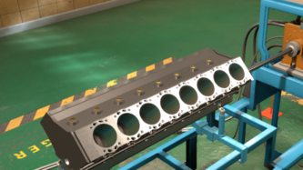
- Inline-5 [I5] - The inline 5 engine is an oddity compared to the two afformentioned engine layouts. In automotive use, the inline 5 engine has had a rather short history, as the engine layout was impossible to use before the advent of multi-point fuel injection systems. As a result, the inline 5 engine was relegated to diesel uses only, until the 1980s. The inline 5 engine's main purpose was to be a compromise between 4 and 6 cylinder engines - combining the simplicity and efficiency of a 4 cylinder engine with the power and smoothness of a 6 cylinder. The inline 5 was popular in cars with transverse engine layouts, due to its short length compared to the 6 cylinder, but improved smoothness and power compared to a 4 cylinder. Thanks to the additional cylinder, the engine experiences less vibrations. However, the difference in smoothness between a 4 and 5 cylinder is less pronounced than the difference between a 5 and 6 cylinder. The 5 cylinder engine is best suited for use in larger, more upscale economy cars, and light trucks. In the game, this engine layout is available from 1970.
- Inline-6 [I6] - The inline 6 engine is the most advanced version of the inline engine in the game. The inline 6 is among the smoothest engines in the game thanks to its primary and secondary balancing, as the 3 pairs of cylinders counter each other's movements. The inline 6 is also a much more powerful engine, thanks to its larger displacement. However, this comes at certain disadvantages. Having 6 cylinders means this engine is the least efficient of all inline engines due to high internal friction. This engine is also harder to work with when using a carburettor or a single point fuel injection system, due to the distance between the 1st and 6th cylinders. The engine is also hard to fit in an engine bay due to its length. As a result of this, the inline 6 engine is mostly used in longitudinally mounted setups. This engine is commonly used in premium and sporty rear-drive cars, and some larger medium duty trucks. In the game, this engine layout is available from the beginning.
V Engines
The V engine is a more complicated engine layout, employing two heads and two cylinder banks joined together in a V of different angles (60° or 90°). The V engine layout is wider than the inline engine layout, however, it is usually shorter, can fit more cylinders, and has a lower center of gravity. In the game, two bank angles are available.
60° Bank Angle
The 60° V engine is more compact than a 90° V engine, at the cost of being more difficult to produce. 60° V engines are favored in transverse engine layouts over the 90° V engine due to their narrower dimensions. In the game, 60° V engines are available in 6 cylinder, 8 cylinder and 12 cylinder layouts.
60° V6
60° V8
60° V12


- V6 (60°) - The V6 is the simplest V engine in game. Compared to a straight 6, this engine layout is much more space efficient due to the compact packaging of a V engine's cylinders, especially one with a narrow bank angle. This comes at a cost of being less smooth than an inline 6 due to a different firing order, more weight and increased complexity due to the use of two cylinder banks and two heads. The 60° V6 is superior to a 90° V6 thanks to its smaller footprint, and superior balance without needing to use a heavy and costly balancing shaft. Nearly all modern V6 engines use a 60° bank angle. A V6 usually has nearly identical power output compared to a straight 6 of the same displacement. This engine type is commonly used in front-drive premium cars and large cars such as minivans and crossovers, as well as some sports cars. In the game, this engine layout is available from 1970.
- V8 (60°) - The V8 is quite a popular engine layout. It provides a good compromise between smoothness, power, size, and cost. Through the use of 8 cylinders, V8 engines can get quite large and powerful. While the V8 is smooth thanks to its cylinder count, it is still not as smooth as the inherently balance inline 6 engine. 60° V8s are quite uncommon, due to their many disadvantages compared to a 90° V8. The 60° V8 is less smooth, and requires the use of balancing shafts, increasing weight, complexity and cost. The 90° V8 on the other hand is more inherently balanced than the 60° V8. The 60° V8 also is more complex due to its narrow bank angle. The 60° V8's main advantage over the 90° V8 is its narrow dimensions, allowing it to be installed transversly in vehicles such as the Volvo XC90, Volvo S80 and Ford Taurus SHO. The 60° V8 is quite a rare engine layout. In the game, this engine layout is available from the beginning.
- V12 (60°) - The V12 is the smoothest, most prestigious engine layout in the base game. It is well known for its association with high end luxury and performance cars. This is due to its enormous power potential and excellent smoothness. Of course, due to the high cylinder count and narrow bank angle, this engine is the most complex and largest engine of the base game. This engine layout's smoothness is the result of having a doubly balanced design, because each cylinder bank is essentially an inherently balanced inline 6, that balance each other out. The V12 engine is only available in a 60° bank angle, which is the smoothest and most common bank angle for V12 engines. The V12 engine layout is exclusively found in high end luxury vehicles and supercars. In the game, this engine layout is available from the beginning.
90° Bank Angle
The 90° V engine has a lower center of gravity and is easier to build compared to 60° V engines, at the cost of having a larger footprint. 90° V engines are mostly used in longitudinal engine layouts in larger cars and trucks. In the game, 90° V engines are available in 6 cylinder, 8 cylinder and 10 cylinder layouts.
90° V6
90° V8
90° V10
90° V16


- V6 (90°) - The V6 is the simplest V engine in game. Compared to a straight 6, this engine layout is much more space efficient due to the compact packaging of a V engine's cylinders, however, the 90° V6 is less compact than the narrow bank angle 60° V6. The advantage of the wider bank angle of the 90° V6 is that its center of gravity is lowered, due to the engine having a shorter height. This can be beneficial for performance application, and was the main reason as the why the Honda NSX used a 90° V6 in its transverse mid-engine layout. In other areas of comparison, the 90° V6 loses out against the 60° V6. The 90° V6 is not as balanced and is less smooth than the 60° V6, thus requires a balancing shaft. The 90° V6's main appeal is for its simpler to produce bank angle, and modularity with larger 90° V8 engines. In the real world, V6 engines were originally developed from V8 engines with two cylinders removed, and still to this day, some V6 engines are designed like that, such as the GM Vortec 4300 V6. The 90° is most commonly used in light duty trucks, and old base model versions of V8 equipped cars. In the game, this engine layout is available from 1970.
- V8 (90°) - The 90° V8 engine is the most ubiquitous 8 cylinder engine. This engine is well reknown for its balance between smoothness, power, size and cost. Using 8 cylinders, the engine can achieve good balancing and power through large displacements. Although this engine layout is smooth, it is not as smooth as the inherently balanced inline 6 engine. The 90° V8 is superior to the 60° V8 in nearly every metric save size. The 90° V8 is smoother than the 60° V8 without needing a balancing shaft, the 90° V8 has a lower center of gravity compared to its 60° counterpart, and it is cheaper to produce than a 60° V8. As a result, the 90° V8 is the most common V8 type, being the engine of choice for classic American full size cars, medium and heavy duty trucks, as well as various luxury and performance vehicles from Europe and Japan. Another advantage of the 90° V8 is the ability to equip two different crankshaft designs, which is discussed more in depth here. In the game, this engine layout is available from the start.
- V10 (90°) - The 90° V10 is not a common engine type. Most of its use has been in sports and super cars, as well as heavy duty trucks. This engine type is smoother, but more expensive compared to the 90° V8. The 90° V10 isn't as smooth compared to its more balanced 72° counterpart (which is not available in Automation), but it is much more common, thanks to its modularity with much more popular V8s, for example, the Ford Triton V10 (6.8 L) is essentially a Modular V8 (5.4 L) with two extra cylinders. Modern V10 performance and super cars like the Dodge Viper, Lamborghini Huracan and Audi R8 all use these 90° V10s.
- V16 (90°) - The 90° V16 is the single most prestigious and expensive engine in game. Due to its ridiculous cylinder count and size, this engine is known for massive power and near-perfect smoothness. In the game, the V16 is only available for players who have purchased the V16 Supporter Pack. V16 engines are very rare powerplants, with most production V16 engines dating back to pre-war luxury vehicles such as the Cadillac-16, and one hypercar still in development, the Devel Sixteen, using a V16 engine based off of two conjoined GM 6.2 liter LS V8s. In the game, this engine layout is available from the start.
Boxer Engines
The boxer engine layout resembles the V engine layout in the fact that it employs two seperate cylinder banks and heads, making it just as complex. However, the main difference lies in the block itself being perfectly flat, like a 180° V engine, and the crank design, being unlike the crank of a V engine. A boxer engine uses one crankpin per piston, while a V engine uses one crankpin for two opposing pistons. A flat 180° V engine is known as a flat engine, which, as previously stated, is different from a boxer. Due to the different crankpin design, the pistons of a flat engine and of a boxer engine move in different manners. The flat engine's pistons move in the same direction. If one piston moves away from the crankshaft, the opposing piston will move towards the crankshaft, and vice-versa. On the other hand, the boxer engine's pistons move in the opposite direction, with both opposing pistons moving towards or away from the crankshaft. In the game, boxer engines are available in 4 cylinder and 6 cylinder layouts.
Boxer-4

Boxer-6


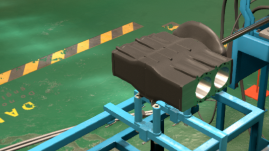
- Boxer-4 [H4] - The boxer 4 is the simplest non-inline engine in the game. Compared to an inline 4, the boxer 4's short length and squat layout gives this engine the best center of gravity in game, as the engine can be mounted far in the rear of a car's engine bay, leading to superior weight distribution. The boxer 4 is also much smoother than an inline 4 due to the horizontally opposed layout of the cylinders. The boxer 4 engine's downsides compared to the inline 4 engine includes the inability to be mounted transversely, as the engine's heads would get in the way. The boxer 4 is also more complex than an inline 4 due to the use of two cylinder banks. The boxer 4 engine's short length still allows it to be used in front wheel drive applications, using a longitudinal FWD drivetrain. Another disadvantage of the boxer 4, which is shared with other boxer and flat engines, is the difficulty in servicing such engines. The engine's heads are cast off to the sides rather than the top of the engine, making it more difficult to access items such as spark plugs. The boxer 4 engine has historically been used in a variety of cars, such as the rear engined Volkswagen Beetle and front engined Subaru Impreza economy cars, or sporty/sports cars such as the mid engined Porsche Boxster and front engined Subaru WRX. These cars take advantage of the small dimensions of a boxer 4 engine to use a longitudinal engine mounting (in the front or rear). In the game, this engine layout is available from the start.
- Boxer-6 [H6] - The boxer 6, alongside the inline 6, V12 and V16, is one of the smoothest engine layout in game. The superior smoothness of the boxer 6 in comparison to a V6 engine is due to the lack of vertical movements of the pistons. The two cylinder banks of the boxer 6 engine also cancel out the vibrations caused by each other, due to the opposing movements of the pistons. The boxer 6, like its 4 cylinder counterpart, is a low and short engine, meaning it also has the advantage of superior center of gravity and weight distribution, especially when compared to the long and tall inline 6. The disadvantage of a boxer 6 compared to an inline 6 is its added complexity due to the use of two cylinder banks as opposed to one. The disadvantage of a boxer 6 compared to a V6 is the inability to be transversly mounted due to the boxer 6's width in comparison to a V6, especially a narrow-angle V6, however, with its short length, a boxer 6 engine can still be compatible with a longitudinal FWD setup. The boxer 6 engine has had limited use in automotive history, however, like the boxer 4, this engine setup is best known for use in Porsche and Subaru vehicles. The boxer 6 has been used in Porsche's 911 and Cayman sports cars, as well as its 959 supercar, in mid and rear engine configurations. Boxer 6 engines have also been used in Subaru's front engined sports cars, sedans and crossovers, such as the SVX, Legacy/Liberty, and B9 Tribeca. The boxer 6 also had been used for a short period of time by American manufacturer Chevrolet during the 1960's, in their Corvair rear-engined sedan. In the game, this engine layout is available from the start.
Block Material
A cast iron inline-4 engine block

An aluminium inline-4 engine block

The block material tab is where you can select out of which material your engine's block will be cast out of. These different metals exhibit a variety of properties that may make them more suitable for different applications.
- Cast Iron - The most basic material for building engine parts, cast iron uses an iron-carbon alloy with a low melting point, which can be poured into a mold and hardened into any shape. Cast iron is a cheap material that is easy to work with. Cast iron is also quite durable and rugged. One overlooked advantage of cast iron blocks is that they are better at muffling engine sounds. The downsides of cast iron is its weight, which makes it unfavorable for use in sports cars. Cast iron engine blocks are still common on trucks and SUVs.
- Aluminium - A more advanced choice of material for building the engine, using aluminium is lighter weight compared to cast iron. Aluminium engine blocks have superior emissions ratings thanks to their porous nature, essentially trapping pollutants within the engine. These are aluminium's main advantage compared to cast iron, as it has plenty of disadvantages, such as a weaker, less durable engine block, and it is harder to work with, as the aluminium engine block requires iron cylinder sleeves. In the real world, not all aluminium engines use iron cylinder sleeves, however, these cylinder sleeves do help with durability. The light weight alone makes it a favored choice of classic sports cars. Nowadays, however, aluminium engines are very common among most modern cars on the market.
- Aluminium Silicate (AlSi) - Aluminium silicate is a specialized aluminium alloy, which corrects the weaknesses of a pure aluminium block. AlSi is superior at bearing engine stresses (not as good as cast iron however). AlSi blocks are easier to produce than an aluminium block, as they are able to dispense the use of iron cylinder sleeves. Like aluminium, AlSi is also porous, allowing it to trap pollutants. This comes at a cost of elevated material costs in comparison to aluminium. Aluminium alloy engine blocks (such as AlSi) are common on most modern cars.
- Magnesium - Magnesium is a lightweight metal related to aluminium. Magnesium engine blocks are the lightest compared to the aformentioned block types, and they are the best at muffling sound. Magnesium engine blocks are just as porous as aluminium and AlSi, alloying the magnesium engine block to reduce pollution. Magnesium's disadvantages comes from its costs, higher than any other material, and difficulty in working with. Due to magnesium's corrosiveness, magnesium cannot come into contact with engine coolant. Another disadvantegous property of magnesium is that iron can cause magnesium to corrode faster. These two drawbacks of magnesium means that all coolant lines and cylinder sleeves must be made from aluminium, using an expensive and complex process known as composite casting. As a result, magnesium engine blocks are only fit for high end sports and supercar applications.
Family Capacity
In the family capacity tab, you can determine your engine's physical dimensions, and maximum displacement. The engine's displacement refers to how much air can fit within the cylinders of the engine, for combustion. The engine's displacement is affected by the bore and stroke of your cylinders, as well as the cylinder count. The cylinder's bore refers to the cylinder's diameter, and the cylinder's stroke refers to the height of the cylinder when the piston is at bottom dead center. The engine displacement is calculated via the formula:
Displacement = π × (bore ÷ 2)2 × stroke × cylinder count
Displacement can be measured using metric values such as cubic centimeters (cc) and liters (L = 1000 cc), or imperial units such as cubic inches (CID). Bore and stroke itself is measured using either millimeters (mm) or inches (in). The minimum and maximum bore and stroke you can use in the game are 50 mm to 120 mm. As evidenced by the equation, the size of your bore and stroke affect displacement in a different fashion. Stroke affects displacement linearly, meaning the displacement changes at the same rate as the stroke changes. On the other had, bore affects displacement quadratically, meaning the displacement changes at an exponentially larger rate than the bore does. Your engine's bore and stroke also affect the engine's external dimensions and weight. A larger bore requires a larger engine block, which is heavier. On the other hand, a larger stroke only has slight effect on your engine's size and weight. There are different advantages and disadvantages to an engine with a larger bore or a longer stroke.
- A larger bore allows for superior engine airflow as it increases surface area of the valves, and greater engine displacement.
- A smaller bore allows for a smaller and lighter engine, a lighter weight valve train (which reduces the chance of valve float at high RPM), and reduces pre-ignition (engine knock).
- A longer stroke allows for greater engine displacement without making the engine much larger or heavier.
- A shorter stroke allows the engine to be smoother and more reliable at higher RPM, as the pistons don't need to more up and down as fast to attain higher RPM.
An engine's dimensions can be described using three terms: square, oversquare and undersquare. A square engine is one with matching bore and stroke sizes. For example, the default engine dimensions in game (86 mm × 86 mm) produces a square engine. Two examples of a square engine would be Toyota's 2JZ I6 and 1UZ V8 engines, Engines used in both sports cars and luxury cars due to their compromise between power, reliability and efficiency. An oversquare engine is one with a bore larger than its stroke. These types of engines are built with high performance and RPM in mind, by using large bores for maximized airflow and short strokes for higher revving. Oversquare engines are also smoother thanks to their shorter strokes allowing for higher revolutions due to reduced piston velocities and better rod/stroke ratios. Two examples of oversquare engines include Nissans SR16VE I4 engine, an engine not so well known, for its 8200 RPM, Variable Valve Timing and top end performance. Another example would be General Motors 350ci short block v8, an engine that found its way into almost all general motors cars during the late 60s-early 70s due to its great design and good performance. Finally, an undersquare engine is one with a stroke larger than the bore. These types of engines are designed for simple packaging and or more torque and efficiency, they develop power and torque lower due to having a longer stroke this makes more leverage on the crank at a gain of rotational resistance due to the pistons traveling furter in the bore, the longer stroke also increases piston velocity at higher rpms due to the increased rod length and stroke length it can effect how the piston travels through the bore. Some examples of such would be the Ford's Barra inline 6, 5.4L modular V8, Honda K24 engine and Nissan KA24 series. Undersquare engines can be found anywhere from utility vehicles to sports cars that just need a little more torque. Almost all Diesel engines are undersquare in design.
Head & Valves
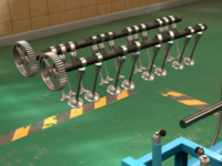
The engine's head contains the valvetrain, the system of valves, springs, and camshaft(s) which control the flow of air, fuel, and exhaust gases in and out of the combustion chamber. The design of the head can greatly affect the engine's costs, performance and fuel economy. In Automation, there are four different types of valvetrains, all available from the beginning of the game. Some of these valvetrains are able to accomodate multiples valves (more than 2 valves per cylinder), improving the airflow of the system.
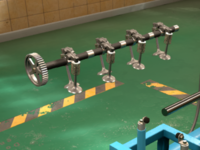
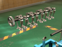
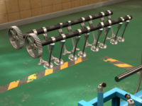
The valvetrain works through a spinning camshaft(s), which rotates once for every two rotations of the crankshaft. The camshaft(s) can be spun by gears connected to the crank (in the case for a cam-in-block [OHV] engine), or by a timing belt/chain spun by the crank pulley (the case of all overhead cam valvetrains). The amount of camshafts an engine has depends on the valvetrain's design and the engine block type. A pushrod system uses one cam for inline, V and boxer engines, while DaOHC and SOHC systems use one cam for an inline engine, but two cams for a V or boxer engine. A DOHC system uses two cams for an inline engine, while using four cams for a V or boxer engine.

Pushrod (OHV) valvetrain

Direct-acting overhead cam (DaOHC) valvetrain
Single overhead cam valvetrain (SOHC 2v)

Single overhead cam valvetrain (SOHC 3v)
Single overhead cam valvetrain (SOHC 4v)
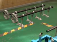
Dual overhead cam valvetrain (DOHC 2v)
Dual overhead cam valvetrain (DOHC 4v)
Dual overhead cam valvetrain (DOHC 5v)


Pushrod [OHV]
A pushrod valvetrain system, also known as cam-in-block or overhead valve, uses a camshaft installed within the engine block. The camshaft is spun by gears connected to the crank, at a rate of one rotation for every two rotations of the crank. The camshaft has little bumps on it known as cam lobes, these are the lobes that cause the valves to be actuated. In a pushrod system, because the camshaft is nowhere near the valves, the lobes of the cam push on metal bars known as pushrods. When the cam pushes up on the pushrod, this causes the pushrod to push up on a small lever known as a rocker arm. When the rocker arm is pushed up from one end, it pushes the other end of the rocker arm down, like a lever. When the other end of the rocker arm is pushed down, it pushes a poppet valve downwards, thus opening the valve. Once the cam lobe passes and stops pressing on the pushrod, the valve spring, a spring which is on the poppet valve, forces the valve up, closing the valve. The cam's lobes are designed to open the correct cylinder's intake and exhaust valve at the right time, following the 4-stroke cycle and the engine's firing order. Intake valves should open during the aspiration stroke, and remain closed until the cycle repeats. On the other hand, exhaust valves should open during the exhaust stroke, and remain closed until the cycle repeats.
The advantages of the pushrod system is its simplicity relative to overhead cam systems. In the game, this valve train is the cheapest to manufacture. The use of a single cam in block allows the system to remain simple, especially in V or boxer engines with two heads instead of one. Keeping the cam in the block also allows the heads to remain small, shrinking the overall dimensions and keeping a low center of gravity. This is one of the reasons why OHV V8 engines, such as GM's LS V8 family, are popular for engine swapping, due to their small physical size relative to their displacements.
The disadvantages of the pushrod system includes poor airflow due to the valves being placed along the center line of the head, limiting power and efficiency. Another disadvantage of this system is that it is restricted to only two valves per cylinder, one intake and one exhaust. This further limits airflow, as four or five valves are more effective at providing increased surface area for airflow. The most prominent disadvantage of a pushrod engine would be its poor high-RPM performance. Due to all the reciprocating mass of the system (cam, pushrods, rocker arms, and valves), as well as the fragility of the pushrods themselves, pushrods quickly encouter valve float towards higher RPMs, meaning they cannot rev high. Pushrod engines are also unable to take advantage of VVL (variable valve lift), however, they are able to use VVT (variable valve timing). Pushrod engines remain in use mostly in large V8 engines designed to be easily mass produced for trucks. The most famous examples of which are the GM LS V8 and Chrysler Hemi V8.
Direct-Acting Overhead Cam [DaOHC]
A direct-acting overhead camshaft uses a camshaft(s) that has been installed in the head(s) rather than in the block. The camshaft(s) is (are) spun by the crankshaft, which spins a crank pulley. The crank pulley cause the timing belt/chain to move, which, in turn spins the cam gear. Spinning the cam gear causes the camshaft to rotate. When the camshaft rotates, its lobes act directly on the valve (hence the name), pushing the valve downwards to open it. Once the camshaft lobe passes, the valve is snapped shut by the valve spring. The camshaft rotates once for every two rotations of the crank.
The advantages of the direct acting overhead cam is its simplicity relative to other overhead camshaft based systems. In the game, this valve train is the simplest to engineer. The use of a single cam which acts directly upon valves allows the system to remain lightweight, giving it good high revving capability due to low reciprocating mass. This limits excessive valve float. This valve train system still retains smaller dimensions, although it is slightly taller than the pushrod system.
The disadvantages of the direct acting overhead cam are quite numerous. They suffer from the same poor airflow as the pushrod due to the valves being placed along the centerline of the head, which somewhat negates the direct acting overhead cam's high RPM capability, as the engine is unable to produce lots of power at high RPMs due to limited airflow. Like the pushrod system, the direct acting overhead cam lacks compatibility with VVL (variable valve lift), or multivalve setups, being limited to only two valves per cylinder. Unline the pushrod system, the direct acting overhead cam system has increased complexity in V and boxer engines due to the use of two cams (one for each head). These disadvantages have mostly phased out the DaOHC from modern automotive use, because the pushrod system has more advantages for the relative simplicity. Meanwhile, single and dual overhead cam systems offer far superior performance and efficiency.
Single Overhead Cam [SOHC]
The SOHC system is similar to the previously mentioned direct acting overhead cam systems, in which there is a single cam sitting on top of the valves within the engine's head(s). The cam is rotated once for every two rotation of the crankshaft by the timing belt/chain which rotates the cam gear. The difference between SOHC and DaOHC is that the cam doesn't directly act upon the valves, instead the cam lobe pushes up on rocker arm (like a pushrod, except the cam lobes directly act on the rocker arms), which causes the other end of the rocker arm to push down on the valve, opening the valve. When the lobe passes, the rocker arm lifts back up, and the valve spring shuts the valve.
One of the SOHC system's advantages over DaOHC is the fact that SOHC has the valves pushed aside from the centerline of the head, helping to improve airflow. By far however, the largest advantage of the SOHC system is the ability to take advantage of multivalve configurations. SOHC systems can use two valves per cylinder (one intake, one exhaust), three valves per cylinder (two intake, one exhaust), or four valves per cylinder (two intake, two exhaust). Having more valves improves airflow, as it allows for greater area to be used for the valve openings. In a two valve per cylinder system, only 50% of the area of the bore can be used for airflow. This means, for example, in an engine with the bore (cylinder diameter) of 86 mm, which has a bore area of 5808.8 mm2, only 2904.4 mm2 can be used for airflow.
Area of bore: A = π × (86 ÷ 2)2 → A = 5808.8 mm2
However, in a system using three valves in place of two, 64% of the bore area can be used for airflow, meaning, 3717.6 mm2 of area can be used for airflow on a 3 valve per cylinder setup. This is an increase of 813.2 mm2 of area compared to the 2 valve system. The best flow however is found using a 4 valve system, which allows 68% of the bore area to be used for airflow. This means that a four valve per cylinder layout can use 3950.0 mm2 of area for airflow, an increase of 232.4 mm2 of area compared to a 3-valve system, and an increase of 1045.6 mm2 of area compared to a 2-valve system. Essentially, multivalve systems are a great advantage for airflow, however, with more valves per cylinder comes higher costs. Multivalves have another, more discreet advantage however. Due to the use of smaller, lighter valves in multivalve systems, their reciprocating masses are decreased, improving high RPM performance and reducing valve float. Outside of multivalve technology, another one of SOHC's advantages is compatability with VVL (variable valve lift).
SOHC's disadvantage is the increased reciprocating mass (compared to DaOHC). Due to the use of rocker arms to actuate the valves, the high RPM performance of an SOHC equipped engine is negatively impacted, with higher likelyhood of encountering valve float. 2 valves SOHC systems are more expensive to design and produce compared to DaOHC and OHV systems. Meanwhile, 3 valve and 4 valve SOHC systems are less performant and efficient compared to DOHC systems. Another one of SOHC's disadvantages, inherent to all overhead cam engines, is the fact that in V and boxer engines, there is an increased complexity due to the use of two cams (one per head). SOHC systems remain in use in budget cars, as their efficiency and power for the price is unmatched by a DOHC system.
Dual Overhead Cam [DOHC]
The dual overhead cam is very similar to the DaOHC system from which it evolved from. The only difference between the two is the fact that the DOHC system uses two direct acting cams within each head instead of just one. Each camshaft is spun by the crankshaft, which rotates the crank pulley. The crank pulley runs the timing belt/chain, which rotates the cam gears, which in turn rotates the camshaft, at a rate of one rotation for every two rotations of the crank. DOHC is different from other overhead cam systems, in which the head contains two cams instead of one. One cam is dedicated to intake valves (known as the intake cam), while the other acts on the exhaust valves only (known as the exhaust cam). Like the DaOHC system which it is based on, the lobe of the camshaft directly pushes down on the valve, causing it to open. Once the lobe passes, the valve is shut by the valve spring.
Like the SOHC system, the DOHC system is available in multivalve configurations. The DOHC system can use two valves per cylinder (one intake, one exhaust), four valves per cylinder (two intake, two exhaust), or five valves per cylinder (three intake, two exhaust - the third intake valve activates above a certain RPM set automatically by the game, improving low end efficiency and high end power). As explained in the SOHC section, multivalve systems are beneficial for air flow. However, one note to be added is that the more valves that are added, the less airflow is gained, in a system of diminishing returns. As explained above, a 2 valve system allows 50% of the bore's area to be used for airflow, while a 4 valve system allows for 68% of the bore's area to be used for airflow. A 5 valve system, however, allows only for 68% of the bore's area to be used for airflow, which is the same as the 4 valve's system. The advantage of 5 valve DOHC over 4 valve DOHC is reduced reciprocating mass, allowing for excellent high RPM performance. Aside from the use of multivalve systems, the other advantages of DOHC include inherently good high RPM performance due to the use of direct acting cams, good airflow due to the valves being cast aside from the head's centerline, the compatability with VVL (excepting 5 valve DOHC heads), and the ability to use VVT on only the intake cam or on both cams, in order to help keep costs low if needed.
DOHC's disadvantage is the sheer cost of engineering and producing such a head type. Although nowadays DOHC engines are the norm, in the past, they were relegated to high performance cars only. DOHC systems get even more complicated in V and boxer engines, which use four camshafts (two per head). Another one of DOHC's disadvantage is the large size and weight of the heads, because the heads need to be large enough to be able to fit two cams. The large weight of DOHC sides cause inline and V engines to have high centers of gravity, which is bad for weight balance, however this downside doesn't exist in boxer engines due to their squat architecture. DOHC engines are the modern standard in passenger cars. DOHC technology has been "trickling down" from higher end sports cars and luxury cars down to common cars during the late 1980's and 1990's. Most old fashioned DOHC engines were using two valve systems only, as they still maintained the inherent high RPM performance of a DOHC system without the added complexity of multivalves.
Head Material
Iron head
Aluminium head


The head material tab is where you can select out of which material your engine's head will be cast out of. These different metals exhibit a variety of properties that may make them more suitable for different applications.
- Cast Iron - The most basic material for building engine parts, cast iron uses an iron-carbon alloy with a low melting point, which can be poured into a mold and hardened into any shape. Cast iron is a cheap material that is easy to work with. Cast iron is also quite durable and rugged. One overlooked advantage of cast iron blocks is that they are better at muffling engine sounds. The downsides of cast iron is its weight, which causes the engine to have a higher center of gravity. Cast iron engine heads are still common on trucks and SUVs.
- Aluminium - A more advanced choice of material for building the head, using aluminium is lighter weight compared to cast iron, which helps to lower the center of gravity. Aluminium heads improve emissions ratings thanks to their porous nature, essentially trapping pollutants within the head. These are aluminium's main advantage compared to cast iron, as it has plenty of disadvantages, such as a weaker, less durable head, and it is harder to work with, as the aluminium engine block requires iron cylinder sleeves. The light weight alone makes it a favored choice of classic sports cars. Nowadays, however, aluminium heads are very common among most modern cars on the market.
- Aluminium Silicate (AlSi) - Aluminium silicate is a specialized aluminium alloy, which corrects the weaknesses of a pure aluminium head. AlSi is superior at bearing engine stresses (not as good as cast iron however). Like aluminium, AlSi is also porous, allowing it to trap pollutants. This comes at a cost of elevated material costs in comparison to aluminium. Aluminium alloy heads (such as AlSi) are common on most modern cars.
Keep in mind that using a different head material compared to the block is not always favorable. It leads to a slight increase engineering time, and causes a reduction in drop in reliability ratings. This is because the different materials have different tolerances and different reactions to stress. However, mixing materials allows to cut costs and improve center of gravity by using a cheaper material in the block, and a more expensive, lighter material in the head(s).
Variable Valve Lift (VVL)
Variable valve lift is a technology which was pioneered by Honda (known as VTEC - Variable Valve Timing & Lift Electronic Control) in the late 1980's and early 1990's. It was first used in the 1989 Honda Integra XSi for the Japanese market. As previously explained, the way a normal valvetrain system works relies on rotating camshafts, which are metal shafts with lobes on them. As the camshaft rotates, the lobe actuates the valve by pushing on the valve, rocker arm, or pushrod (depending on the type of valvetrain used). The shape, or profile, of the cam's lobes affect how much the cam opens. The more aggressive the lobe is, the more is pushed down, which opens the valve more. A more aggressive lobe is good for high RPM power, but bad for low RPM power, smoothness, and efficiency. On the flipside, a mild cam improves low RPM power, smoothness, and efficiency, however, a mild cam chokes airflow at high RPM, and is more likely to incur valve float at high RPM. The solution - to include both a mild and an aggressive cam profile within the cam. This is done through variable valve lift, which has two sets of lobes on the cam. The engine switches to the more aggressive cam profile at higher RPM, helping keep the advantages of a mild cam at low RPM, and the advantages of an aggressive cam at high RPM. The downside to all this is increase complexity, and the fact that VVL is only available on SOHC and DOHC engines.
Now with your engine family all set up and ready to go, you are ready to being producing variants of the engine. Remember that if your engine family has two or more variants, you cannot modify any of the engine family's traits (cylinder count/layout, materials used, or head type).
Bottom End

The engine's bottom end components refers to the engine's crankshaft, connecting rods, and pistons. The components you use affect the engine variant's smoothness, cost, reliability, weight and performance potential. These interal components do not directly affect your engine's power and torque output, but have some bearing on your engine's abilities.
ㅤ

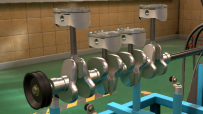
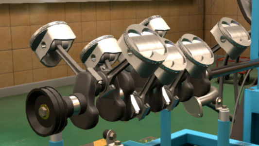
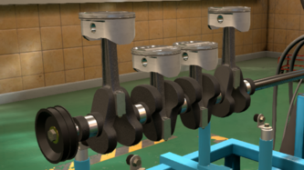
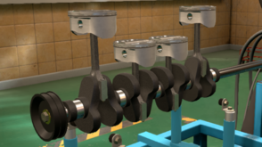
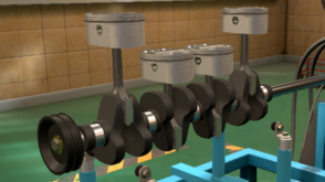
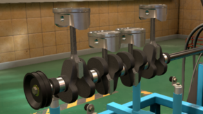
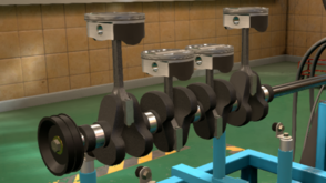
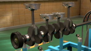
Crank
The engine's crankshaft is the central component of the engine. All of the engine's pistons are connected to the crankshaft. The crankshaft's job is to convert the piston's reciprocating linear movements into rotational movement. The crankshaft itself works by rotating on an axis. The rotation is caused by the pistons up-and-down movements, caused by combustion. As the piston moves from top dead center to bottom dead center, it exerts a downwards pushing force on the crank, causing the crank to rotate 180°. As the piston travels back up to top dead center, it pulls the crank upwards, causing the crank to rotate another 180°, leading to a full 360° degree rotation. The crank's rotation is responsible for essentially powering the car, as it uses the piston's kinetic energy to produce torque (rotational work).

Cast crankshaft

Forged crankshaft
Billet crankshaft


- Cast Iron - A standard cast iron crank. Cast iron cranks are cheap and easy to mass produce. The downsides of a cast iron crank is the fact that it is heavy, which limits higher RPM use. Casting produces the weakest components, which are more susceptible to overtorque stresses due to the casting process. In the casting process, the material is melted, poured into a mold, and then left to cool. While in liquid state, the cast iron's grains expands and spreads randomly. The scattered granular structure of the molten metal then remains frozen in place once the iron cools. This negatively affects the metal's strength.
- Forged Steel - The crank is built using steel that has gone through the forging process. Forged steel cranks are lighter and stronger than their cast iron counterparts, thanks to the forging process. In the metal forging process, the raw metal is heated (but not melted), pounded into a general shape, and then precisely cut into shape. The forging process maintains a finer granular structure, which is made further dense through pounding, allowing for superior resistance to stress. This allows for greater RPM limits for the component, superior engine responsiveness and cuts down on the engine's overall weight. The downsides of a forged cranks is the fact that the forging process is more costly, time consuming, and required specializing machinery.
- Billet Steel - The crank is built using billet steel. Billet steel cranks are the lightest and strongest, thanks to their manufacturing process. Billet components are made from billet steel, a solid, raw block of steel, usually melted down for casting. However, in the manufacturing process of billet steel, the material is compressed in a similar fashioned to the forging process, but rather than being pounded into shape, the compressed block is cut into and carved into shape. This technique is much more labor intensive than forging, and requires high power specialized cutting tools, but provides a finished product with the highest strength and lightest weight thanks to a refined granular structure. Billet steel cranks are optomized for the most refined, highest performance applications.
Cross Plane and Flat Plane Cranks
In a 90° V8 engine, there are two different crankshaft designs - the cross plane and the flat plane crank. These crankshaft designs affect how the engine behaves and sounds, due to their characteristics. The cross plane V8 is associated with American muscle, while the flat plane V8 is associated with Italian exotics.

Cross plane crankshaft
Flat plane crankshaft


- Cross Plane - The cross plane crankshaft is a crankshaft with the four journals arranged in 90° intervals. When viewed from one end, along their axis, the cross plane shaft has a + shape to it, hence the name. Every time the cross plane crank rotates 90°, one of the 8 pistons have a combustion stroke. This, alongside the use of balancing shafts and a firing order which is balanced between the cylinder banks, allows a V8 engine equipped with a cross plane crank to be smoother. This comes with two downsides - this crank design is heavier, which limits high RPM use, and the engine is less powerful at higher RPM due to reduced exhaust scavenging performance.
- Flat Plane - The flat plane crankshaft is a crankshaft with the 1st and 4th journals arranged in a 180° interval from the 2nd and 3rd journals. When viewed from one end, along their axis, the flat plane shaft has a | shaped to it, hence the name. This allows the engine to alternate between the two cylinder banks, firing a cylinder from the left bank, and then the right, and then the left, etc., which improves exhaust scavenging. This crank design can run without balancing shafts, allowing the crank to be lighter weight, which helps with high RPM performance. The main disadvantage of the flat plane crank are the vibrations, which reduce the engine's smoothness.
The traits of the cross plane and flat plane crankshaft are the reason as to why V8 powered luxury vehicles use cross plane cranks, while V8 powered sports cars use flat plane cranks.
Conrods
The connecting rods are responsible for connecting the pistons to the crankshaft. The connecting rods are rigid metal beams, with two ends known as the small end (which connects to the piston), and the large end (which connects to the crankshaft). Conrod failure is the most common cause of engine failure, as the conrods have to be able to withstand the forces being transfered through itself from the piston to the crankshaft, all at various engine speeds.

Cast connecting rods
Heavy duty cast connecting rods

Heavy duty forged connecting rods

Lightweight forged connecting rods

Lightweight titanium connecting rods


- Cast - A standard cast steel conrod. Cast rods are cheap and easy to mass produce. Their downside is their weakness, which causes them to be susceptible to RPM and torque stress. This is all due to the casting process, as described above.
- Heavy Duty Cast - A cast steel conrod, built thicker with more steel. These rods are just as easy to mass produce, however are slightly more expensive than cast rods due to the increased use of material. Heavy duty rods can better withstand torque stress, at the cost of being heavier, which limits smoothness and lowers their RPM limits due to all the reciprocating mass.
- Heavy Duty Forged - A forged steel conrod. These rods are lighter than standard cast rods and more torque resistant than heavy duty cast rods. Their lighter weight enhances the engine's smoothness and ability to withstand high RPM. This comes at a cost however, as this rod is produced in the forging process, which is more expensive and time consuming than the casting process.
- Lightweight Forged - A forged steel conrod that has been machined for weight savings. These rods are lighter than heavy duty forged rods thanks to a machining process in which additional metal is stripped from the rod after forging. The lighter weight of the rods further improves the ability to withstand high RPM, at the cost of torque resistance and even more expensive and time consuming production process.
- Lightweight Titanium - A forged titanium conrod. Titanium is a metal which is light, strong, and expensive, giving it the best resistance to torque and RPM stress. These rods are made in a similar forging and machining process as the lightweight forged steel conrod, with the only difference being an additional step after the machining. Due to titanium being quite reactive, titanium has to be given a protective coating, which gives it a distinct gold shine. The light weight of the titanium rods further improve engine smoothness. The downsides of titanium rods are very high cost and production times.
Pistons
The pistons of the engine are responsible for converting the fuel's chemical energy into kinetic energy. This is done via combustion, which instantly releases the fuel's energy by breaking its molecular bonds, creating a flame front that forces the piston down, transferring the chemical energy into kinetic energy.
Cast pistons
Heavy duty cast pistons
Forged pistons
Hypereutectic cast pistons
Low friction cast pistons
Lightweight forged pistons


- Cast - A standard cast steel piston. Cast pistons are cheap and easy to mass produce. Their downside is their weakness, which causes them to be susceptible to RPM and torque stress.
- Heavy Duty Cast - A cast steel piston, built thicker with more steel. These pistons are just as easy to mass produce, however they cost more due to the additional material needed. Heavy duty pistons can better withstand torque stress, at the cost of being heavier, which limits smoothness and lowers their RPM limits due to the additional reciprocating mass.
- Forged - A forged steel piston. Due to the forging process, these pistons are stronger than their cast counterparts, allowing for superior torque and RPM stress resistance. Forged steel pistons are not lighter than standard cast pistons, as the piston has to use a simplified shape to fit in the forge's die. Forged pistons also have a hidden advantage of reducing pre-ignition (knock), and lowering octane requirements. As a result of the forging process, these pistons are less porous than cast pistons, resulting in a more pollutant, louder engine. These pistons are also more expensive and more time consuming to produce.
- Hypereutectic Cast - A piston cast with a specialized aluminium-silicon alloy. These pistons are almost as easy to mass produce as a standard cast piston, but they are a little more expensive due to the different material type. The hypereutectic piston uses an aluminium alloy which contains a high concentration of silicon. The concentration of silicon is so high that the alloy is said to be past the eutectic point. Thanks to the hypereutectic alloy's properties, this piston type is the best at muffling engine noises and absorbing pollution. In terms of performance, specifically RPM and torque stress, they behave similarly to standard cast pistons.
- Low Friction Cast - A standard cast steel piston, with a specialized low-friction coating on the cylinder walls, and shrunken skirts, made with low friction in mind. Compared to a regular cast piston, these pistons are slightly lighter (and thus slightly smoother) and better at limiting pollution (although not as good as hypereutectic pistons). The biggest advantage of the low friction cast piston is the improved fuel efficiency of the engine. Internal engine friction is one of the main causes in loss of efficiency, and low friction pistons help to counter this. The disadvantages of low friction cast pistons are that they produce more noise (not as loud as forged pistons), and are more fragile, thus making them more prone to RPM and torque stress.
- Lightweight Forged - A forged steel piston, machined for lightest possible weight. The pistons are lighter, smoother, and capable of the highest RPM limits compared to a typical forged steel piston. This comes at a cost however, as this piston type produces more pollution, more noise, and is the most expensive and time consuming piston type.
Variant Capacity
Using the variant capacity slider, you can modify your engine variant's displacement. Building multiple variants of one engine family with various displacements is much cheaper, quicker, and easier to manufacture than having to design multiple engine families. This is because each variant shares a lot of architecture in common with the other variants of the engine family. Having multiple displacement options within a single engine family can make the engine more useful for a variety of applications. As stated before:
- A larger bore allows for superior engine airflow as it increases surface area of the valves, and greater engine displacement.
- A smaller bore allows for a lighter weight valve train (which reduces the chance of valve float at high RPM), and reduces pre-ignition (engine knock).
- A longer stroke allows for greater engine displacement.
- A shorter stroke allows the engine to be smoother and more reliable at higher RPM, as the pistons don't need to move up and down as fast to attain higher RPM.
One thing to note is that modifying the engine variant's capacity has no effect on the engine's outer dimensions, and little effect on its weight.
In the real world, an example of one engine having variants with multiple displacements would be the GM LS V8 family. The engines range from 4.8 L (293 CID) to 7.0 L (427 CID), however, they all share the same basic architecture.
Top End (Head)

On the top end design tab, you are able to tune your engine's compression ratio, camshaft profile(s), and equip variable valve timing (VVT).
Compression
The engine's compression ratio is a measure of how much the pistons reduce the cylinder's internal volume at top dead center. For example, the ratio of 9.6:1 means the volume of the combustion chamber is 9.6 times smaller when the piston is at top dead center. When you increase the engine's compression ratio, power & torque output is improved across the entire operating range of the engine. Another advantage of a high compression ratio is increased fuel efficiency, as when the combustion mixture (air and fuel) is compressed, it is able to combust faster and the engine can extract more mechanical energy from the combustion.
The main downside of a higher compression ratio is the higher likelyhood of pre-ignition. Pre-ignition (also known as knock or pinging) is a negative effect in which the air & fuel mixture combusts before the piston reaches top dead center during the compression stroke. The pre-ignition is caused by the extremely high temperatures of a highly pressurized system, which, when hot enough, can cause compression ignition. This negatively impacts the engine's power output, reliability, and efficiency. Strong enough engine knock can physically destroy the engine's components. In order to counter knock, one must either use a lower compression ratio, or use higher octane fuel. Another downside of a higher compression is a higher output of pollutants, due to the increased temperatures of the combustion chamber. These higher temperatures cause nitrogen and oxygen, two main components of the atmosphere, to combine together in various molecules collectively known as NOx (nitric oxides, includes nitric oxide [NO] and nitrogen dioxide [NO2]). These NOx gases are the precursors to acid rain.
Cam and VVL Profiles
The cam profile and VVL profile sliders modify the cam lobes of your camshaft. As previously explained, the cam lobes are tear-drop lumps which actuate the valves while the cam spins. The cam's profile refers to the shape of the lobes, specifically how much the tear-drop shape of the lobe extends. A more aggressive lobe extends farther, and causes the valves to be pushed down more, thus opening the valve more. The cam profile you select affects how your engine sounds at idle. A more aggressive cam makes your engine idle rougher and "sputter" more. You can listen to difference yourself in the engine testing page.
Advantages of a low (mild) cam profile:
- Improved engine efficiency - As the valves are less open, they are better at containing the engine's combustions, improving efficiency.
- Optimized for low engine speed - Due to the valves being less open, they are able to properly contain the engine's combustions at low RPM. This improves low RPM torque and power output.
- Smoother engine operation - The engine runs smoother and idles at lower RPM with a mild cam, as the combustion is more controlled, especially at low engine speed.
- Reduced pollution - With the valves being more shut, less unspent hydrocarbons are able to escape the combustion chamber.
Disadvantages of a low (mild) cam profile:
- Poor airflow at high engine speed - Due to the valves being less open, less air is able to quickly enter and exit through the valves at high RPM, limiting high RPM performance.
- Increased likelyhood of encoutering valve float - valve float is an undesirable effect which happens when the valve springs aren't strong enough to counter the inertial mass of the valves, in order to shut them in time. Valve float happens at high engine speeds when the valvetrain components are all moving and rotating at high speeds. A mild cam is more likely to encounter valve float because the mild camshaft lobes require the valves to open and shut faster.
- Increased likelyhood of knocking - A low camshaft profile is more likely to knock, this is because the combustion chamber has a harder time dissipating heat when the combustion chamber remains more contained. The increased temperatures are ideal for pre-ignition.
Advantages of a high (aggressive) cam profile:
- Optimized for high engine speed - With the valves being more open, the engine has superior airflow, which allows for the engine to keep breathing at a higher RPM, potentially outputting more power.
- Improved cooling - With the more open air flow of an aggressive cam profile, the combustion chamber is able to dissipate more heat, allowing for the engine to maintain a higher compression ratio
- Reduced valve float - With an aggressive cam profile, the valves are more open, which gives more time to close the valve springs at the right time.
Disadvantages of a high (aggressive) cam profile:
- Poor engine efficiency - With the valves being more open, the engine's combustions cannot be well contained, leading to a loss in efficiency.
- Poor performance at low engine speed - With the valves being more open, the engine's combustions cannot be well contained, which negatively impacts engine output at low RPM.
- Rougher engine operation - The engine cannot smoothly operate due to the less contained combustions. The engine also needs to idle at higher RPM.
- Increased pollution - With more open valves, the likelyhood of unburnt hydrocarbons escaping the combustion chamber increases.
If your engine family is equipped with VVL (variable valve lift), you will be able to manipulate a second camshaft profile. The VVL camshaft profile is only actuated at higher engine RPM, with the switch-over point being automatically determined by the game. Due to the aformentioned characteristics of mild and aggressive cam profiles, and due to the fact the VVL profile is used at higher engine speeds, the VVL profile is always more aggressive than the regular cam profile. Usually a difference of 15 to 25 between the regular cam and VVL cam smoothens the transition point, allowing your engine to maintain more consistent torque output. Too large of a difference between the regular cam and VVL cam causes your engine to lose power in the middle of its operating range, while too little of a difference between the regular cam and VVL cam makes no performance difference, and doesn't justify the additional costs of VVL.
Variable Valve Timing (VVT)
VVT is a different type of variable valve technology, compared to VVL. Rather than manipulating the camshaft, VVT manipulates the cam gear, modifying the timing of the cam. The cam timing refers to when the valves are opened and closed during the combustion cycle, as opposed to how much they are opened (which is what VVL deals with). In Automation, VVT operates on the principle of cam phasing, which modifies the angle of the camshaft rotation (relative to the rest of the engine timing system [crank pulley, timing belts/chains]). Cam phasing changes when the valves open and close, but doesn't change how long the valves remain open and closed. Cam phasing is also considered a stepped adjustment, meaning one timing is used at low RPM, while another timing is used at high RPM.
The game automatically uses an optimum valve timing. With VVT, the game automatically adjusts both timing profiles, and the switchover point, selecting choices which optimize low engine speed efficiency and high engine speed power. With a DOHC engine, you are able to use VVT on one cam (the intake cam) instead of both cams, to help with reducing costs.
Forced Induction
In order for the combustion to happen, the engine needs to introduce air into the combustion chamber. This can be done in two ways, naturally, or through the use of forced induction
Natural Aspiration

In a naturally aspirated engine, air is introduced into the engine by the aspiration stroke itself. When the piston descends from top dead center to bottom dead center (after the exhaust stroke), a vacuum is produced in the cylinder. Due to this vacuum, air naturally flows into the cylinders in order to equalize the cylinder's internal air pressure with that of the atmosphere's. The maximum air pressure a naturally aspirated engine can have in its cylinders is equal to atmospheric air pressure (approximately 15 psi, or 1 bar). This air is then used by the engine to combust the fuel, as the atmosphere's oxygen is a crucial component of combustion reactions. A typical combustion reaction uses oxygen and a fuel (most likely a hydrocarbon), and outputs carbon dioxide and water. The combustion of gasoline, for example, is formulated as such:
25O2 + 2C8H18 → 16CO2 + 18H2O
Note: C8H18 is octane, one of the primary hydrocarbon ingredients of gasoline/petrol, often used to represent gasoline in chemical reactions
Turbo Charger

A turbocharger, also known as a turbosupercharger, is essentially just an air compressor. The turbo is run by the engine's exhaust gases. As the exhaust gases exit the engine and flow down the exhaust header, the gases flow through the turbine. As the gases flow, they cause the turbine to spin, which spins the compressor. As the compressor spins, it aspirates and compresses air. The pressurized air is then sent through the engine's intake, and used for combustion. The pressure of the compressed air is known as boost, which is a measure of the how much higher the air within the engine's cylinders is higher compared to atmospheric pressure. For example, a boost pressure of 9.11 psi means there is up to 24.11 psi of air pressure within the cylinders, as the boost pressure is added onto regular atmospheric pressure (about 15 psi). Turbochargers slighly muffle engine noise, depending on the size of the turbo. When a turbocharged engine is running, a slight whining sound can be heard, this is the sound of the compressor spinning faster and faster.
ㅤ

Type
The type of aspiration method your engine uses. The turbocharger option unlocks in 1975.
Setup
The setup of your turbocharger(s). This depends on your engine type and layout. As of now, in the game, inline engines can only use a single turbo, meanwhile V and boxer engines can only use a twin turbo setup.
The setup tab also includes which turbo types you can use. As of now, the only two turbo types available are standard turbos with journal and ball bearings. The bearing type affects the turbo's cost and performance. The turbo's bearings are the joints which connect the fans of the compressor and turbine to a rotating shaft and the rest of the turbo assembly. The bearing's job is to facilitate the rotation of a shaft by reducing friction. The bearing type used can affect your turbo's lag, meaning when the turbo is spooled up enough to start producing boost.
- Journal Bearing - A simple journal bearing is used for the the central shaft. A journal bearing is essentially two metal rings, one within the other, than spin on an axis. This design is the cheapest and simplest type, however, it produces more friction. This additional friction makes it harder to spin the turbo, leading to more turbo lag.
- Ball Bearing - A ball bearing is used in place of the journal bearing. A ball bearing is built almost like a journal bearing, except multiple small metal balls lie inbetween the two metal rings, hence the name. The ball bearing cuts down on friction, improving turbo performance. Its downsides are increased cost. By the mid-1980s, ball bearing type turbos essentially become a straight upgrade to journal bearing types.
Intercooler
The intercooler's job is to cool the pressurized air coming from the compressor side of the turbo. As air is compressed, its temperature increases, as stated by the gas-law equation:
PV = nRT
P refers to the gas's pressure (in this case, air), V represents its volume, n represents the quantity of gas molecules present, R represents the ideal gas constant, which can be represented in many forms, and T represents the temperature of the gas. As the value of P increases, it is logical that T also increases, due to the equation. This is also proven experimentally, as when gases are compressed, their molecules are forced closer and closer together. This causes them to move faster and faster, thus raising temperature (temperature itself is essentially an average of the speed of particles).
The intercooler works like a radiator, in which it dissipates heat through massive surface area. Due to the intercooler's structure, it has many exposed surfaces, which are cooled by ambient air as the car moves. As the compressed air flows through the intercooler, it dissipates its heat, transferring it to the intercooler. The intercooler, in turn, dissipates that heat.
Cooler intake air has many advantages. The cold air helps maintain a colder combustion chamber, preventing pre-ignition. Cooler air is also more dense, which means more air can be provided to the combustion chamber, improving power output.
The size of the intercooler in game is determined by a slider which measures the intercooler's size by power rating. A larger intercooler rated for more power doesn't necessarily produce more power, however, it allows for more power to be made. A larger intercooler is better at cooling air than a smaller intercooler, due to the larger surface area, and allows for more boost to be produced as it is better flowing. However, larger intercoolers are more expensive, heavier, and take up more engine bay space than a smaller intercooler. Sometimes, larger intercoolers are simply unecessary, especially for low boost economical turbocharged motors.
Presets
The presets affect compressor and turbine diameter, AR ratio, and maximum boost. These presets are optimized for engine efficiency or performance, depending on what you want the engine to do. Presets form a good baseline for your turbo tune, however, it is recommended to mess with the turbo tune yourself to fully optimize your engine's performance. For a good guide in turbo tuning, visit the game forum.
Compressor
As previously stated, the compressor's job is to take in atmospheric air, and pressurize it. This is done using a spinning fan which forces air through the compressor, into the intercooler. The compressor's size affects spooling time (the time it takes to generate boost) and maximum boost. The compressor's minimum and maximum sizes depend on how large the engine itself is. A small compressor is well suited to a small displacement engine, while a large compressor is suited to a larger displacement engine.
Large Compressor advantages
- Superior high RPM performance as the larger compressor is able to move more air for high RPM use.
- Higher maximum potential boost pressure due to being able to pressurize more air.
Small Compressor advantages
- Superior low RPM performance as the smaller compressor is lighter and can spin up faster.
- Superior throttle response, due to faster spool.
Large Compressor disadvantages
- Less predictable performance due to turbo lag.
- Inferior low RPM performance due to turbo lag.
Small Compressor disadvantages
- Reduced maximum boost potential due to inability to pressurize enough air
- Inferior high RPM performance due to airflow restriction.
Turbine
As previously mentioned, the turbine's job is to spin the compressor. The turbine does this through the use of flowing exhaust fumes. The passing exhaust gases cause the turbine to spin, and through a shaft and bearings, the spinning turbine causes the compressor to spin. Just like the compressor, the turbine's size affects spooling time, boost production, and exhaust gas airflow. The turbine's minimum and maximum sizes depend on how large the engine itself is. A small turbine is well suited to a small displacement engine, while a large turbine is suited to a larger displacement engine.
Large Turbine advantages
- Superior high RPM performance, as the larger turbine is less restrictive on exhaust gas airflow.
- Higher power potential, due to superior exhaust gas airflow.
Small Turbine advantages
- Superior low RPM performance, as the smaller, lighter weight turbine is able to spin up faster.
- Superior throttle response, due to faster spool.
Large Turbine disadvantages
- Inferior low RPM performance, as there aren't enough exhaust gases built up to properly spin the turbine.
- Inferior throttle response, due to turbo lag.
Small Turbine disadvantages
- Inferior high RPM performance, as the turbine is too restrictive towards exhaust gases.
- Inferior potential power, due to limited exhaust gas flow.
AR Ratio
The turbo's AR ratio is the ratio between the diameter of the inlet and outlet of the compressor (inlet is where atmospheric air enters, outlet is where pressurized air exits) and the ratio between the diameter of the inlet and outlet of the turbine (inlet is where the exhaust gas enters, outlet is where the exhaust gas exits). This ratio can affect turbo performance just like the size of the compressor and turbine. An AR ratio of less than 1.00 means the outlet is smaller than the inlet, while an AR ratio of greater than 1.00 means the outlet is larger than the inlet. At an AR ratio of 1.00, the compressor and turbine maintain a constant internal diameter.
Larger AR Ratio
- Superior high RPM performance due to improved airflow.
- Superior potential perfornance, due to the ability to pressurize more air and allow easier exhaust gas flow.
- Inferior low RPM performance, as the larger AR ratio doesn't funnel exhaust gas as effectively, leading to turbo lag.
- Reduced responsiveness, due to turbo lag.
Smaller AR Ratio
- Superior spool time. Due to the compressor and turbine outlets being smaller than their respective inlets, exiting air is sped up, allowing compressed air to flow through the turbo system faster, and allowing exhaust gases to flow faster through the turbine, spooling the turbo faster.
- Faster spool times result in superior throttle response and low RPM performance
- Inferior high RPM performance, as the smaller AR ratio is more restrictive towards airflow.
- Maximum potential performance is reduced as the turbo isn't capable of high maximum boost.
Max Boost
The maximum boost of the turbocharger refers to how much additional air pressure the turbo can provide. Although the maximum boost value itself is set, the turbo itself is not guarranteed to always produce maximum boost. The amount of boost actually produced depends on a variety of conditions, such as how much throttle the engine is running at, the RPM which the engine is running at, and of course, the turbocharger's and intercooler's own charcteristics (such as how fast it can spool and how much maximum boost it can phyiscally produce, or how much air the intercooler can cool and let flow). Greater maximum boost outputs can potentially output more power (as long as the turbocharger and intercooler can handle it), at the cost of higher internal pressure, which puts more strain on the engine block and increases the chance of pre-ignition, engine efficiency, and more turbo lag (as the turbo needs to spool more to produce higher boost). Excessive boost can also put pressure on the fuel system, especially if your engine is using carburetors. Low maximum boost isn't as powerful (as less air is entering the cylinders), however, it can improve efficiency relative to a naturally aspirated engine, and allows for the engine to retain high compression ratios. Low maximum boost doesn't require large, slow turbos, meaning a small, less capable turbo will do.
Fuel System

The fuel system of the engine is tasked with transporting fuel into the engine. There many different methods in doing so, each with their advantages and disadvantages. This tab is very important for your engine variant, as it can determine your engine's purpose and target demographic.
Fuel Systems
As previously mentioned, the fuel system is what takes fuel from the gas tank into the engine. Two main categories of fuel systems exist, which each fuel the engine using very different methods. Within these categories exists even more variety in fuel system.
Carburetors
Carburetors work through fully mechanical means. The carburetor's job is to intake air and fuel, mix them together, and send the mixture into the cylinders, through an intake manifold and the intake valves, which is then used for combustion. In general, carburetors are simple and cheap. Carburetors were the preferred fuel system for cars for a long time, from the advent of the automobile in the late 19th century, all the way to the 1980's, where fuel injection technology made its way to regular cars. Carburetors work using one or more venturies (barrels). Air enters from the top (downdraft) or from the side (sidedraft), while fuel enters from a float (a mini fuel tank for the carburetor). The float is either installed on the side of the carburetor (downdraft) or on the top (sidedraft). The air and fuel mix together at the venturi, which is a restriction in the flow of the air and fuel. At the venturi, the air-fuel mix is sped up due to the Bernoulli principle, in which a flowing object (liquid or gas) passing through a tightening restriction will flow at a faster rate. This is because the venturi's restriction causes a pressure increase behind it, which forces the air-fuel mix to spray out at higher speed. The resulting high speed spray is at a lower pressure. Since the 1990's, carbureted cars have fully been replaced by fuel injected cars. In automation, five varieties of carburetors exist, which perform their jobs in different manners.
Single Barrel Carburetor (Downdraft)
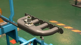
Single barrel carburetor
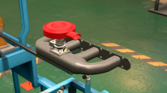
Single barrel carburetor with standard intake
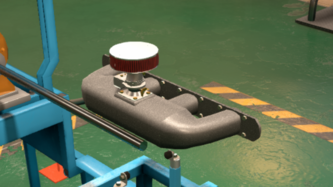
Single barrel carburetor with performance intake
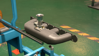
Single barrel carburetor with racing intake


The single barrel carburetor is the simplest fuel system in the game. This carburetor design uses only one venturi (barrel) to deliver the air-fuel mixture to the engine. The use of one barrel greatly simplifies this fuel system, however, this comes at a cost, as this carburetor design offers rather weak performance due to poor flow of the air-fuel mix. This design is also unable to vaporize a rich fuel mixture, meaning its maximum air-fuel ratio is 13.2:1. This carburetor was used in most post war and 1950's cars, eventually being replaced by the more advanced twin barrel carburetor in the 1960's. This fuel system is available throughout the entire game. This carburetor is based off of the Holley single barrel carburetor, an American design.
Single Barrel Eco Carburetor (Sidedraft)
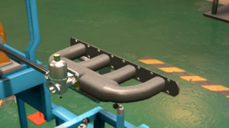
Single barrel sidedraft carburetor
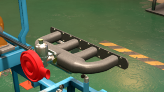
Single barrel sidedraft carburetor with standard intake
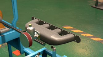
Single barrel sidedraft carburetor with performance intake

Single barrel sidedraft carburetor with race intake


The single barrel eco carburetor is slightly more complex than a standard single barrel carburetor, due to its sidedraft design. In a sidedraft design, the air intake is on the side of the carburetor, and the float (the camber which delivers fuel to the carburetor) is on top. This is the opposite of the configuration a downdraft carburetor uses, which has a side mounted float and top mounted air intake. This carburetor uses only one venturi to deliver air-fuel mix in the engine. The main appeal of this carburetor design is its superior efficiency compared to a downdraft single barrel carburetor. This carburetor allows the engine to output nearly equal power to its downdraft counterpart, while using a much leaner fuel mixture, thus saving fuel. This carburetor's downside is low power potential due to the single barrel design, and the inability to function with a rich fuel mixture. This carburetor's maximum air-fuel ratio is 14.2:1. This fuel system is available throughout the entire game. This carburetor is based off of the SU (Skinner's Union) single barrel carburetor, a British design.
Twin Barrel Carburetor (Downdraft)
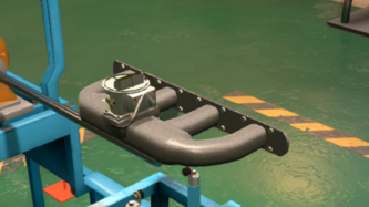
Twin barrel carburetor
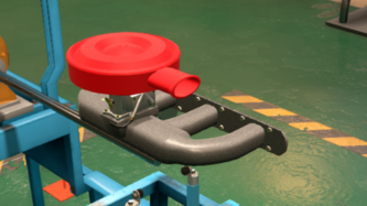
Twin barrel carburetor with standard intake

Twin barrel carburetor with performance intake
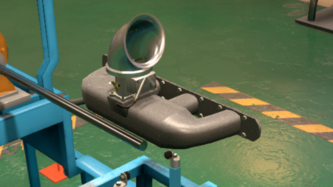
Twin barrel carburetor with race intake


The twin barrel carburetor is an evolution of the single barrel carburetor, now with a secondary barrel. This design improves the carburetor's airflow, which results in performance and efficiency gains. The twin barrel carburetor's two barrels are designed for different purposes. Both the primary large barrel and secondary small barrel runs when the engine is at full throttle and needs maximum air and fuel for performance. The secondary small barrel runs when the engine is just cruising or idling, improving emissions and fuel economy. With the use of two barrels, a richer fuel mixture can be used. The additional barrel comes at a cost, as this carburetor design is more complex than both the downdraft and sidedraft single barrel carburetors. This carburetor's maximum air-fuel ratio is 12.9:1. This carburetor was used in cars from the 1960's all the way to the early 1990's. This carburetor is based off of the Hitachi twin barrel carburetor, a Japanese design.
Quad Barrel Carburetor (Downdraft)
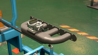
Quad barrel carburetor

Quad barrel carburetor with standard intake
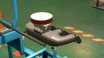
Quad barrel carburetor with performance intake
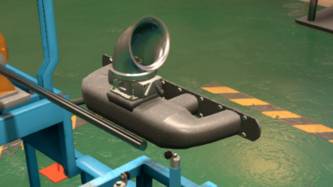
Quad barrel carburetor with race intake


The quad barrel carburetor is the most advanced downdraft style carburetor in game. This carburetor works similarly to the twin barrel carburetor, but with double the barrel count. With the increase in barrel count, comes superior combustion control, which allows for improved performance and efficiency. The four barrels of this carburetor operate sequentially, meaning only one barrel opens at 25% throttle, two at 50%, three at 75%, and all four at 100% throttle. This allows the engine to be both economical, non-polluting and powerful, depending on the demands of the operator. The doubling of barrel count also improves the carburetor's air flow and allows it to use a richer air-fuel mix. As the most advanced downdraft carburetor, the quad barrel carburetor is also the most complex. This carburetor's maximum air-fuel ratio is 12.7:1. This carburetor design was used in the late 1960's to the 1990's, restricted mostly to use for higher end cars and performance cars due to the cost of the system, and adequacy of the twin barrel carburetor. This carburetor is based off of the Holley 4-barrel carburetor, an American design.
DCOE Carburetor (Sidedraft)

DCOE carburetor
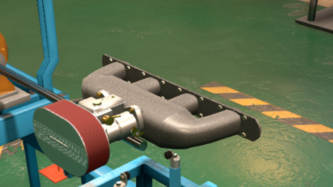
DCOE carburetor with performance intake
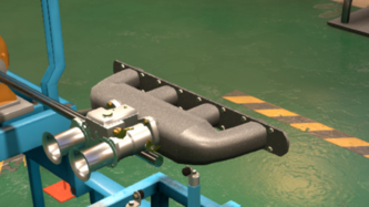
DCOE carburetor with race intake


The DCOE carburetor is a specialized high performance carburetor design. This carburetor is a sidedraft design, like the single barrel eco carburetor, however, unlike the eco carburetor, it employs two barrels instead of one. Unlike the downdraft twin-barrel carburetor however, these two barrels are both large, being optimized purely for high performance. Unlike any other carburetor design mentioned above, this carburetor employs two air channels, one for each barrel. This, alongside the sidedraft design of the carburetor, maximizes airflow. Even with half as many barrels, the DCOE carburetor exhibits great flow comparable to that of the quad barrel carburetor. The DCOE is also able to use a rich fuel mixture. The main disadvantages of the DCOE carburetor is its cost, poor fuel efficiency and emissions due to the use of two equal-size barrels that always run together, and the fact that the DCOE carburetor cannot equip a standard intake, limiting the use of the DCOE carburetor to performance cars only. This carburetor's maximum air-fuel ratio is 12.5:1. This carburetor was primarily used in high performance cars of the pre-fuel injection era. The DCOE carburetor is based off of the Weber DCO-E carburetor, an Italian design. DCO stands for "Doppio Corpo Orizzontale", which translates to "Double Body Horizontal", referring to the sidedraft design and twin air channels. The E in the designation refers to how the carburetor was produced, using die-cast aluminium.
Fuel Injection
Fuel injection systems are quite different from carburetors. Rather than relying on the Bernoulli principle to spray jets of air-fuel mix through venturies, the fuel injection system uses one or more injection nozzles which sprays the fuel into a fine mist. The holes of the injection nozzle can be thought of as mini-venturies. These are very small holes in which high pressure fuel is forced through them. The main difference between various fuel injection systems is the location the injectors themselves. Fuel injection systems have existed for a long time, seeing use in military aviation of the Second World War. Fuel injection first came to gasoline powered cars in the post war era, using mechanically controlled injection units found as options for high end cars. In the early 1980's, electronic fuel injection began to become the industry standard, due to fuel injection's superior efficiency and reduced emissions. By the 1990's, nearly all cars run on fuel injection. To this day, fuel injection is the standard for cars.
Mechanical Fuel Injection (MFI)
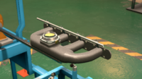
Single throttle mechanical fuel injection
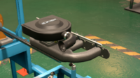
Single throttle mechanical fuel injection with standard intake
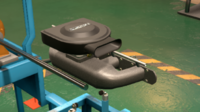
Single throttle mechanical fuel injection with performance intake
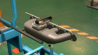
Single throttle mechanical fuel injection with racing intake
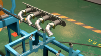
Throttle-per-cylinder mechanical fuel injection
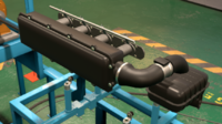
Throttle-per-cylinder mechanical fuel injection with standard intake
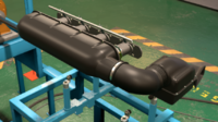
Throttle-per-cylinder mechanical fuel injection with performance intake
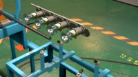
Throttle-per-cylinder mechanical fuel injection with racing intake


Mechanical fuel injection relies on complex mechanical parts to run a series of injectors. One injector is placed on each cylinder's intake port, where the intake manifold meets the engine itself. The injectors spray fuel into a fine mist, which then mixes with air that enters through the throttle body and intake manifold. The throttle body(ies) control the engine's airflow, opening and closing depending on power demand. Mechanical injection works using either a single throttle body, or one per cylinder. Mechanical injection's advantages compared to carburetors includes improved engine response, smoother running engine (as the fuel delivery is more consistant), and good airflow, as the throttle plate and intake manifold are the only obstacles air has to pass through. Through a more complex throttle-per-cylinder setup, the engine can achieve superior responsiveness. The downsides of mechanical fuel injection are its sheer cost and complexity, as the injections have to be run through a complex mechanical system which manages the timing of each injector. This fuel system unlocks in 1965. Mechanical fuel injection was mainly found on high end sports cars of the 1960's and 1970's. During the 1980's, this injection method was slowly phased out as electronic fuel injection became more and more advanced. This injection system has a maximum air-fuel ratio of 12.5:1. The mechanical fuel injection system is based off of Bosch Mechanical Injection, a German design.
Electronic Fuel Injection (Single Point)
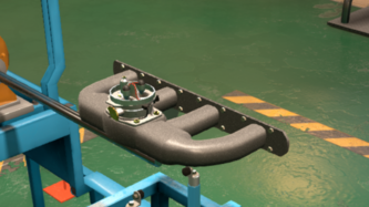
Single point electronic fuel injection
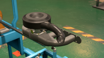
Single point electronic fuel injection with standard intake
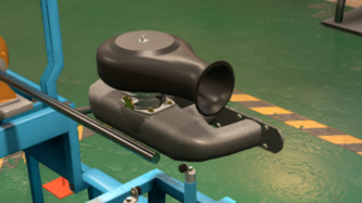
Single point electronic fuel injection with performance intake
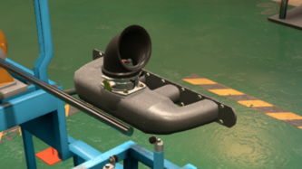
Single point electronic fuel injection with race intake


Single point electronic fuel injection (SPEFI) is a sort of compromise system between carburetors and electronic injection. Like a carburetor, the SPEFI system sprays fuel into the intake manifold, where it mixes with air and enter the engine through the intake ports. However, instead of using mechanically controlled barrels, the SPEFI system uses a computer controled injector. The appeal of SPEFI comes from the fact that a lot of tooling designed for carburetors, such as air intakes, can be re-used for the SPEFI system. SPEFI also has a host of advantages inherent to fuel injection, such as superior throttle response and efficiency. While SPEFI is superior to carburetors in that regards, it is inferior to mechanical injection, or other injection systems. SPEFI's advantage in regards to other injection systems is its simplicity, due to the fact it borrows tooling from carburetor-based systems and only uses one single injector instead of one injector per cylinder. SPEFI (and other electronic injection systems) hold an advantage over mechanical injection - the ability to respond to engine conditions in real time. Performance wise, SPEFI equipped engines offer performance similar to that of a 4-barrel carburetor. SPEFI has a maximum air-fuel ratio of 12.8:1 This fuel system unlocks in 1978. SPEFI is mainly found on various cars of the very-late 1970's, 1980's, and early 1990's. By the end of the 1990's, electronic fuel injection had fully evolved from single point systems to multi point systems. SPEFI is based off of Bosch K-Jetronic, a German design.
Electronic Fuel Injection (Multi Point)
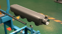
Single throttle multi point electronic fuel injection
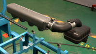
Single throttle multi point electronic fuel injection with standard intake

Single throttle multi point electronic fuel injection with performance intake
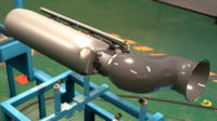
Single throttle multi point electronic fuel injection with racing intake


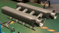
Twin throttle multi point electronic fuel injection
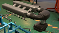
Twin throttle multi point electronic fuel injection with standard intake

Twin throttle multi point electronic fuel injection with performance intake
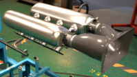
Twin throttle multi point electronic fuel injection with racing intake


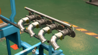
Per-cylinder throttle multi point electronic fuel injection
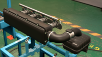
Per-cylinder throttle multi point electronic fuel injection with standard intake
Per-cylinder throttle multi point electronic fuel injection with performance intake

Per-cylinder throttle multi point electronic fuel injection with racing intake


Multi point electronic fuel injection (MPEFI) is an advancement of SPEFI that combines the best of electronic injection and mechanical injection. Like the mechanical injection system, MPEFI uses one injector per cylinder. The injectors are positioned within the engine's intake ports, right behind the intake valves. This allows for even more precise fuel control compared to SPEFI and mechanical injection, and cools the combustion chamber by spraying in liquid fuel, unlike the SPEFI which vaporizes its air-fuel mixture in the intake manifold. MPEFI, like all other electronic fuel injections, is able to respond to engine conditions in real time, an advantage it holds over mechanical injection. Disadvantages of MPEFI include its increased cost and complexity due to the increased amount of injectors, and increased dependence on computer controls. MPEFI engines are capable of serious performance, especially for their value. MPEFI has a maximum air-fuel ratio of 12.5:1. This fuel system unlocks in 1985. MPEFI is mainly found on cars of the late 1980's, 1990's and 2000's. It can still be found on cheaper vehicles today. MPEFI is based off of Bosch KE-Jetronic, a German design.
Direct Injection
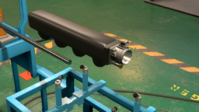
Single throttle direct injection

Single throttle direct injection with standard intake
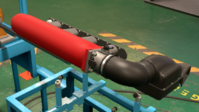
Single throttle direct injection with performance intake

Single throttle direct injection with racing intake


Twin throttle direct injection
Twin throttle direct injection with standard intake
Twin throttle direct injection with performance intake
Twin throttle direct injection with racing intake


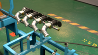
Per-cylinder thottle direct injection
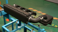
Per-cylinder thottle direct injection with standard intake
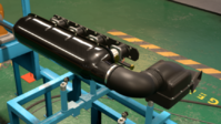
Per-cylinder thottle direct injection with performance intake
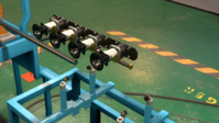
Per-cylinder thottle direct injection with racing intake


Gasoline direct injection (GDI) is the most advanced form of fuel injection available in game. Based on diesel direct injection (DDI), GDI improves upon the MPEFI system on two accounts - fuel control and weight. In the GDI system, the injectors are moved from within the intake ports, to within the cylinders themselves. The injector can be installed on the top of the cylinder, next to the sparkplug, or it can be placed on the cylinder wall. Thanks to the injector's position within the combustion chamber, the GDI system is best at keeping the combustion chamber cold, as it directly injects liquid fuel into the chamber. The injector's position also grants a direct injection engine excellent resposiveness, superior efficiency, and minimal pollution. The GDI system is also lighter weight than all other fuel systems, as it doesn't need a cast iron intake manifold, and uses a lighter plastic manifold. The disadvantage of GDI is simple - massive engineering and production costs. This system is so expensive and hard to build that despite its objective superiority to MPEFI, MPEFI remains a solid alternative to GDI solely due to the costs. The costs come due to the fact GDI uses a very high pressure fuel system, GDI injectors usually spray fuel at 2000 psi (138 bar). GDI also uses rather expensive electronics to operate the injectors, which demand more than 12 volts of electricity to run. GDI injectors themselves are also expensive units themselves, not only do they have to withstand high fuel pressures, they must also be able to withstand all the pressure and high temperatures of combustion that takes place within the cylinders. GDI engines are able to be pushed to greatest power outputs. GDI has a maximum air-fuel ratio of 11.8:1, the richest mixture out of all injection systems. This fuel system unlocks in 2001. GDI has recently become the standard of the automotive industry.
Configuration
Each fuel system can be setup with various configurations depending on the engine block type and cylinder count. Multiple carburetors can be installed on an engine, and injection systems can use different throttle body arrangements. Inline and boxer engines can use one single throttle body, or one throttle body for each cylinder, while V engines can use one throttle body, two throttle bodies, or a throttle-per-cylinder setup (SPEFI can only use one throttle body, and mechanical injection cannot use two throttle bodies). For example, Chrysler used to sell a 440 CID (7.2 L) V8 equipped with three twin-barrel carburetors, and Nissan's RB26-DETT engine used a throttle per cylinder MPEFI injection setup. Using more advanced configurations can bring performance improvements, at the expense of greater cost and reduced fuel efficiency.
Intake
The engine's intake is the component which is responsible for introducing air into the engine. This is done using in various different methods depending on the fuel system and induction method. The intake itself is a chamber which holds air or air-fuel vapor and introduces it through the intake ports into the engine (when the intake valves open). The intake regulates airflow through the use of thottle plates. The more the engine operator presses down on the gas pedal, the more air flows into the engine, creating more power. In carbureters, the throttle plates are located at the base of the carburetor, right at the connection with the intake manifold. This means the throttle plate regulates the flow of the air-fuel mix into the manifold. When the air-fuel mix makes it past the throttle plate, the heat of the manifold (usually made of cast metal) causes the air-fuel mix to vaporize. It is then aspirated into the engine through the intake valves. The SPEFI system works similarly to carburetors in that regard, as the injector sprays onto the hot cast metal manifold, causing the fuel mist to be vaporized and mixed with air before being aspirated by the engine.
In the case of mechanical injection, MPEFI and GDI fuel systems, the fuel doesn't enter the manifold at all, instead being injected directly into the intake ports or combustion chamber. This means the manifold only transports air instead of air-fuel mix. The intakes of these systems use throttle bodies which are seperate from the fuel system itself. These throttle bodies contain the throttle plates, which open when the operator of the engine steps on the gas pedal to allow in more air. As discussed in the configuration section, some intake systems can have more than one throttle body.
One of the intake's jobs is to help muffle engine noises and clean the air before letting it in the engine. While an engine is operating, it is possible to accidentally suck in particles such as dirt, sand, gravel, or other small objects such as insects. If these items were to enter the fuel system and engine, they could cause damage such as clogging a carburetor barrel or injector, or, worst case scenario, enter the combustion chamber and break a valve or score the cylinder walls and piston. In order to prevent this, intakes are equipped with filters. If you've ever serviced your car's airbox (or any car's), you may have replaced an air filter and noticed how dirty they can get. In Automation, three intake types can be used:
- Standard - The intake is well filtered and muffled, making the engine as quiet and well protected as possible. This reduces noise and increases reliability at the cost of power output, as the muffling and filtration blocks some air from reaching the engine.
- Performance - The intake is filtered, but sound muffling components are removed. This allows the engine to aspirate more air and still remained well protected. The comes at the cost of a noisier engine and slight reliability penalty.
- Race - The intake has no filters or muffling, for maximum airflow and weight saving. The makes for a very loud and much less reliable engine, however it can help further improve power output.
These three intakes also affect the sounds your engine makes. At the engine testing page, you will be able to listen to these sounds yourself.
Fuel Type
What Gasoline is
Gasoline (or petrol) is a mixture of hydrocarbon based chemicals, and additional additives that may improve performance or reliability. Gasoline is made from a mix of various liquid low molecular weight unsaturated hydrocarbons called alkanes. Alkanes are molecules that consist of a chain of single-bonded carbon atoms. All these carbon atoms have a total of four bonds, with the bonds not occupied by a carbon atom being instead occupied by a hydrogen atom. Alkanes have a simple naming scheme, starting with a prefix denoting the amount of carbon atoms in the chain, and the suffix -ane. For example, octane is an alkane with eight (oct-) carbon atoms. Alkanes also have a simple generic chemical structure, of CnH2n+2, which means for every carbon atom, there is twice as many hydrogen atoms, and two additional hydrogen atoms. The types of alkanes found in gasoline include pentane (C5H12), hexane (C6H14), heptane (C7H16), and octane (C8H18). Heavier alkanes are found in more viscous fuels such as diesel and kerosene, such as dodecane (C12H26). The types of hydrocarbons found in different gasoline grades affect the fuel's quality and pre-disposition to pre-ignition (engine knock).
Gasoline Quality
Gasonline quality is measured using its octane rating. The fuel's quality is measured in comparison to a benchmark fuel made of a mixture of two hydrocarbons: iso-octane and n-heptane. Iso-octane (C8H18), also known as 2,2,4-trimethylpentane, is a monomer of octane. Like octane, this molecule has 8 carbon atoms and 18 hydrogen atoms, but, unline octane, this molecule is arranged differently. The main structure of this molecule is a 5-carbon chain (hence the pentane name). The second carbon atom has two methyl (CH3) groups bonded to it, while the fourth carbon atom has one methyl group. This gives it a distinct structure from octane. Iso-octane has an octane rating of exactly 100. N-heptane, on the other hand, is any monomer of a 7-carbon alkane. It has an octane rating of exactly 0. The quality of gasoline can be quantified by two different testing procedures, which uses the aformentioned iso-octane and n-heptane as benchmarks: RON, MON and AKI.
RON (Research Octane Number)
The RON number is determined by running the fuel on a test engine. The test engine runs at 600 RPM, and has variable compression. After the test is run, the tested fuel is compared to various benchmark fuels. These benchmark fuels are made of different proportions of mixed iso-octane and n-heptane. Using the benchmark fuel's iso-octane content percentage, the fuel's octane rating can be determined. For example, if the fuel being tested has similar performance to a benchmark fuel made of 95% iso-octane and 5% n-heptane, then the tested fuel is assigned an octane value of 95 RON. This is the scale used in most of the world.
MON (Motor Octane Number)
The MON number is determined using an identical test to the RON test. The difference is that additional parameters are added which further pushed the tested fuel to its limit. The tested fuel mixture is pre-heated before testing, and the test engine runs differently. The test engine runs at 900 RPM, and is also equipped with variable ignition timing. Usually, the MON rating of a fuel is 8 to 12 points lower than the RON rating (there is no correlation between RON and MON numbers). The MON rating is sometimes used alongside the RON rating.
AKI (Anti-Knock Index)
The AKI value is determined by taking the average of the RON and MON value (R+M/2). This is the scale used in the United States, Canada and Central America.
Leaded Fuel
Leaded fuel uses a special additive which helps boost the octane number - tetraethyl lead (C8H20Pb). Tetraethyl lead (TEL) works to reduce pre-ignition through the breaking of its carbon-lead bond. The lead bonds and neutralizes with radical intermediates in the combustion reaction. The downside to this improved gas performance is the production of leaded pollution. Lead pollution is toxic to humans and animals, especially organic lead pollutants such as TEL. TEL can easily poison someone due to its volatility (ease of vaporization) and its ability to pass the blood-brain barrier. TEL can also cause reduced sterility in males and birth defects. Another downside of leaded gas is the inability to use a catalytic converter on an engine which runs off of leaded gas. This is because the lead would choke and disable the catalytic converter by coating its reactive surfaces with lead deposits. In nearly the entire world (except Algeria, Iraq and Yemen) leaded gas has been banned, due to its health hazards and the widespread implementation of catalytic converters. The ban of leaded gas took places in the mid-to-late 1970's.
Fuel Mixture
The fuel mixture is the ratio of air to gas the engine runs on. The number you set is the target fuel mixture of the engine, however, in the real world, an engine may run richer that needed for a variety of reasons. The fuel mixture is measured in grams, in X grams of air per 1 gram of gasoline. The stoichiometric, or ideal, fuel ratio is 14.7 g of air to 1 g of fuel. This is reflected by the equation representing the combustion of gasoline:
25O2 + 2C8H18 → 16CO2 + 18H2O
An AFR (air-fuel ratio) of greater than 14.7:1 is considered lean, while an AFR of less than 14.7:1 is considered rich.
- Leaner Fuel Mixture - Allows the engine to be more fuel efficient. This comes at the cost of power output as less fuel is burnt, and a hotter combustion, which increases the chance of knock and produces more NOx pollution.
- Richer Fuel Mixture - Allows the engine to put out more power (to a point), and keeps the combustion cool, reducing pre-ignition. This comes at the cost of efficiency, as with more fuel, the combustion has less time to burn all the fuel. This also produces more unburnt hydrocarbons as pollution. If the mixture is too rich, it can overwhelm the fuel system, cutting power and preventing combustion all together. Each fuel system type has a different maximum fuel mixture richness. A fuel system can run a richer fuel mixture than its limit if the engine is turbocharged. The additional air pressure provided by the turbocharger facilitates the use of very rich fuel mixtures. Running such a rich fuel mixture will cause your engine to backfire while running it in the testing page.
Ignition Timing
The ignition timing of the engine refers to the timing of the firing of the spark plugs. The spark plug is fired right when then engine finishes the compression stroke and initiates the combustion stroke. In an engine that isn't knocking, the spark plug firing is what causes combustion. The default timing value of 50 means the spark plug fires when the piston is at top dead center, right in between the end of the compression stroke and the beginning of the combustion stroke. An advanced timing (>50) means the spark plugs fire right at the end of the compression stroke, while a retarded timing (<50) means the spark plugs fire after the beginning of the combustion stroke (as the piston starts moving back to bottom dead center, the spark plug still hasn't ignited the air-fuel mixture. These different timing setups have different advantages and drawbacks.
- Advanced Timing - Optimized for high RPM, engines with advanced timings can potentially produce slightly higher power figures. Advanced timing also benefits engine efficiency. This comes at the cost of an increased risk of pre-ignition.
- Retarded Timing - Optimized for low RPM, engines with retarded timings can potentially produce better low RPM power figures. Retarded timing also reduce the chance of pre-ignition. This comes at the cost of reduced efficiency.
RPM Limit
The RPM limit refers to the limit of the engine's speed. RPM (revolutions per minute) is a measure of many times the crankshaft rotates every minute. The amount of RPMs of the crank is based off of the average speed at which the piston is moving up-and-down from bottom to top dead center and length of the stroke which the piston is travelling. The relation between the piston's average speed and the RPM is shown in these equations:
Average Piston Speed = 2 × stroke × (RPM ÷ 60) — Note: using mm for the stroke measurement will give an average piston speed in mm/s
RPM = [Average Piston Speed ÷ (2 × stroke)] × 60 — Note: average piston speed and stroke measurements have to use the same measurement units (i.e. APS in cm/s, stroke in cm)
According to the equations, higher RPM and longer strokes results in a higher piston speed. The pistons themselves are limited in how fast they can go before physically being destroyed. The weight and strength of the pistons is what determines how fast they can travel. This is explained in more depth here.
The main advantage of having a higher RPM limit is potentially increasing power output. Power is essentially a measure of the rate at which work is performed, or work over time. Power output is calculated from torque output, which is measured by the rotational work of the engine's crankshaft. The relatioship between power, torque and RPM is show in the equations for power output:
hp = (tq × RPM) ÷ 5252 — for imperial horsepower, torque value expressed in lb. ft
kW = (tq × RPM) ÷ 9.5488 — for kilowatts, torque vale expressed in Nm
However, producing high RPM power can be quite challenging. For one, as previously mentioned, the engine's internal components must be able to withstand the stresses of high RPM. The engine's valve train must also be able to withstand high RPM. If the RPM is too high for the valve train type or cam profile, you may run into valve float problems. The second challenge is designing an engine that is able to provide consistent torque output even at high RPM. This means having a valve train, induction and fuel system that can provide adequate air flow at high RPM. Sometimes, even if the internals of the engine can withstand high RPM, the engine isn't able to produce any meaningful power and torque at high RPM, making a high RPM limit useless. An engine with a high RPM limit is always less reliable on average compared to an engine with a lower RPM limit, as the lower RPM limit is less stressful to the engine.
Exhaust System

The final step before you complete your engine design is configuring the exhaust system. The exhaust system is responsible for evacuating exhaust gases, and can be set up for maximum power output, or maximum efficiency.
Headers
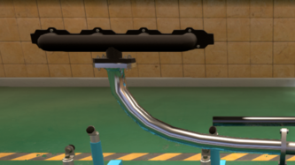
Cast log header
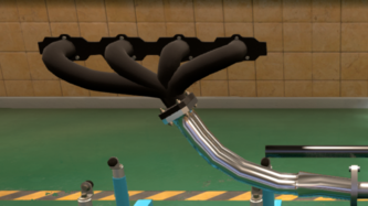
Short cast header
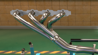
Tubular header
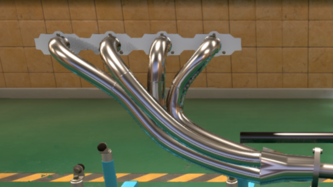
Long tubular header
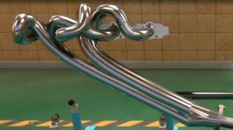
Race tubular header


The exhaust headers' job is to extract exhaust gas from the engine, and funnel the gases into the exhaust pipe. A header design with superior airflow allows for more power to be made, as a better flowing header extracts more exhaust gas from the combustion chamber, thus allowing more space for air, producing more power. More advanced exhaust headers can take advantage of an effect known as exhaust scavenging, in which exhaust pulses from the engine "bounce" between the walls, causing the gas to swirl. As the gases swirl, they are able to "suck" out exhaust gases and help the engine aspirate fresh air.
- Cast Log - Simplest exhaust header design. A simple series of metal pipes, very cheap to build, at the cost of poor airflow.
- Short Cast - More advanced cast header. Now with more flowing design, which allows the header to take advantage of exhaust scavenging, leading to improved airflow. Still quite cheap to build, but slightly more complex than cast logs.
- Tubular - Lighter, better flowing exhaust header, made of welded stainless steel rather than cast iron. With superior airflow to the short cast header, and superior construction (as stainless steel has a smoother surface than cast iron), this header allows for more power at the cost of increased complexity and inferior noise muffling, as cast iron is better for sound deadening.
- Long Tubular - Longer exhaust tubes further improve airflow and scavenging effects, at the cost of increased complexity and noise.
- Race Tubular - With its complex shape, this header design can only be built by hand (meaning no mass production). This header guarrantees the best airflow due to the flowing nature of the pipes, as a well as their equal length, which allows the exhaust pulses to be perfectly timed for maximized exhaust scavenging.
Note - Turbocharged engines can only use short cast headers
Exhaust
This tab is for configuring the basic configuration of the exhaust system. A single exhaust refers to an exhaust system with only one exit. In an inline engine, this means the exhaust pipe starts from the end of the header, and ends at the exit. In V and boxer engines however, which have two headers (one per cylinder bank), two exhaust pipes merge into one. Inline engines can only use single exhaust, while V and boxer engines can use both a single or dual exhaust. The dual exhaust has superior airflow due to the fact that each individual pipe only has to deal with half of the exhaust gas volume. This comes at a downside of increased cost and weight.
Bypass valves are a series of valves which control the sound muffling of the exhaust system, allowing for a closed and opened setting. The closed setting is for normal driving, allowing the engine to be as quiet as possible, and the open setting is for performance driving, allowing the engine to be as powerful as possible. The downside of this system is increased cost and complexity. These bypass valve systems are commonly found on modern sport and supercars with configurable exhausts, which may have more than two setting.
Exhaust Diameter
The exhaust diameter refers to how wide the exhaust pipe is. The optimal exhaust diameter depends on the engine's displacement and purpose. A wider diameter exhaust pipe is less restrictive on airflow, leading to potentially more power, at the downside of increased noise, cost and weight, and decreased engine efficiency. Wider exhausts are essentially only used on sports cars. A narrow diameter exhaust pipe, on the other hand, is more restrictive on airflow, leading to a power decrease. However, it has the advantage of better noise muffling, efficiency, and decreased cost and weight. Narrow diameter exhaust are perfectly suited for standard cars. An exhaust system with too wide of a diameter can actually cause the engine to lose power, as the exhaust system loses desirable scavenging effects. An exhaust system with too narrow of a diameter may choke the engine, causing little power to be produced, and potentially even pre-ignition. Remember, what is considered narrow diameter, average diameter, and wide diameter depends entirely on the engine's displacement. For example, a 63.5 mm (2.5 in) diameter pipe is quite wide on a 1.6 liter engine, but quite narrow on a 6.0 liter engine.
Catalytic Converter
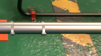
No catalytic converter
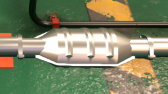
2 and 3 way catalytic converter
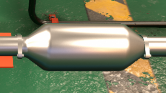
High flow 3 way catalytic converter


The catalytic converter is responsible for cutting down on engine pollution. This is done through a series of reactions which converts pollutants to less harmful gases, which are catalyzed by the various precious metals such as palladium, iridium and platinum found within the catalytic converter's interior. The afformentioned precious metals work as catalysts in various reactions. A catalyst is a part of chemical reaction that facilitates the reaction (usually by lowering activation energies). These catalysts are tasked with assisting in three different reactions which neutralize three main pollutants:
Oxidation of carbon monoxide — 2CO + O2 → 2CO2
Oxidation of unspent hydrocarbons — hydrocarbon + O2 → CO2 + H2O
Reduction of nitrogen oxides (NOx) into nitrogen gas
- 2CO + 2NO → 2CO2 + N2
- hydrocarbon + NO → CO2 + H2O + N2
- 2 H2 + 2NO → 2H2O + N2
Catalytic converters cannot be installed if the engine runs on leaded gas. The TEL additive (tetraethyl lead) reacts poorly with the catalytic converter's precious metals, causing lead deposits to build up in the converter, making it ineffective and choking the exhaust system.
Catalytic Converter Types
- None - No catalytic converter is installed. Allows for a cheaper, lighter weight and better flowing exhaust system, as catalytic converters are quite expensive due to the use of precious metals. This comes at the cost of bad pollution ratings. This is the only option you can use if your engine runs on leaded gas. In the real world, selling a production car without a catalytic converter in the mid-1970's or later would be illegal.
- 2-Way - The most primitive catalytic converter type. Poorest airflow, but the cheapest catalytic converter option. The 2-way converter gets its name from the fact that it only neutralizes two pollutants - carbon monoxide and unspent hydrocarbons. This means it still lets out quite a lot of pollution due to the inability to neutralize NOx. This is the catalyst type predominantly used in the 1970's.
- 3-Way - An improvement to the 2-way catalytic converter, with improved airflow, and the ability to catalyze the reduction of NOx emissions. This comes at the downside of greater expense compared to the 2-way catalytic converter. This catalytic converter was predominantly used starting in the early 1980's, when new emissions standards required vehicles to cut down on nitrogen oxide emissions, a known precursor to acid rain.
- 3-Way (High Flow) - The most advanced catalytic converter design available, which functions the same as the standard 3-way catalytic converter system, but with improved airflow for potentially greater performance and engine efficiency. This catalytic converter design is the current industry standard.
Mufflers
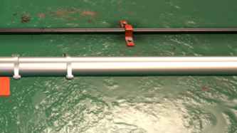
No muffler
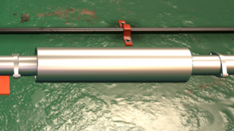
Baffled muffler
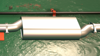
Reverse flow muffler
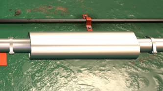
Straight-through muffler


Mufflers are devices which act as a sound muffling chamber (hence the name). The objective of the muffler is solely to cut down on engine noise, which can be quite uncomfortable. If you've ever been in a car with broken mufflers or one that has been straight-piped (had its mufflers removed), you will know how the loud droning of the exhaust may reduce overall comfort of the car. The three different muffler designs in Automation cut down on sound in different ways. The reduction of noise comes at a cost of engine performance, because the muffler's design chokes airflow. In Automation, up to two mufflers can be installed on your exhaust system.
- None - No muffler is installed. Allows for a cheaper, lighter weight and better flowing exhaust system. This comes at the cost of no noise insulation, leading to a loud engine.
- Baffled - The baffled muffler is the cheapest and simplest muffler. Inside the housing, a row of perforated plates (plates with holes in them) are placed in the path of exhaust flow. This reflects back engine noise, at the cost of reducing airflow.
- Reverse Flow - The reverse flow is more complex, but quieter muffler. Inside the housing, a perforated pipe with two 180° bends carries the exhaust gases, while forcing the engine noises to escape the pipe itself and reflect within the chamber. This muffler gets its name from the pipe's design. Due to its two 180° bends, it causes the exhaust gases to flow in the opposite direction of the exit before turning around again towards the exit. This muffler has both superior sound muffling and airflow qualities compared to the baffled muffler
- Straight-Through - The straight-through muffler is the simplest and best flowing muffler. Inside the housing, a straight perforated pipe allows exhaust gas to easily flow. The perforations of the pipe causes some sound to remain trapped within the housing, however this muffler is the least quiet.
Your engine's muffler setup can affect your engine's sound. Try it for yourself by testing your engine with no mufflers, a single muffler, and a dual muffler setup.
With your exhaust system now set up, your engine is considered finished. Of course, you can always go back and modify any engine parameter you may want to fix.
Engine Design Summary

With your engine now a (hopefully) running piece, you can now review your engine's performance and statistics. This information can be very useful to help you go back and fine-tune your design to maximize what your engine is capable of.
Engine Statistics
The engine statistics tab gives you all of your engine's stats (as the name implies). This includes a description of the engine (its displacement [in cc or CID], head design and cylinder count/layout), and various engine parameters, such as:
- Maximum power output (and the RPM where it happens)
- Maximum torque output (and the RPM where it happens)
- Maximum RPM (redline)
- Performance index (a measure of how desirable your engine would for those seeking to buy sports cars)
- Required cooling (which affects engineering of the car itself)
- Smoothness
- Responsiveness
- Noise
- Reliability
- Yearly maintenance costs
- Thermal efficiency - the engine efficiency refers to the percentage of how much of the fuel's chemical energy is converted into mechanical energy. The rest is wasted as heat and noise or lost to internal friction. The highest theoretical limit to a combustion engine's efficiency is about 60%, while the most efficient production-feasible gas engines are about 40% efficient.
- Fuel octane requirement (minimum octane rating required to run the engine properly without pre-ignition)
- Emissions (a measure of how much pollutants are produced by the engine)
- Weight
- Engine volume/footprint (how much physical space the engine takes)
- Material costs
- Production time (in months)
- Engineering time (in months)

Variant Statistics
Keep in mind that you can view your engine's statistics at any time, on any tab (only after your engine variant's design is completed). This variant statistics tab contains the same information as the engine statistics tab of the engine summary page. Placing your cursor over any number will show what the number refers to. Whenever you make an engineering change to your engine, certain statistics will change. These new statistics will show on the left column of numbers, while the old stats show up on the right. If the change positively affects a certain stat, the new number will show up as green and the old number red. For example, a change was made on the example motor which reduced noise from 20.5 to 18.9, which improves the engines comfort. If the change you made negatively affects a certain stat, the new number will show up as red, while the old number shows up green. For example, the same change which reduced noise of the engine also increased the engine's weight, from 137.4 kg to 138.7 kg. In the variant statistics tab, you are also able to compare statistics between the current engine variant you are working on, and any past engine you've built. The left column will show your current engine's stats, while the right column shows the other engine's stats. The superior statistics are green, while the inferior statistics are red. At the bottom of the tab are three buttons. The stack of papers saves your current engine tune. After pressing it, you can make various modifications to your engine. It will compare the new modifications to the held engine design. If you're satisfied with your new tune, you can press the "not-allowed" symbol to delete the old held tune. If you do not like your new tune, you can simply revert to the old tune by pressing the undo button to the right.
Engine Testing
The engine testing tab is where you can run your engine on an engine dynamometer, which measures power and torque output at the crank. It also allows you to listen to all the sounds your engine makes. On this tab, there are three dials - one which measures torque and power output, one which measures air pressure within the engine, and one which measures RPM. The first and third are quite self-explanatory. The second dial (air pressure), measures both the engine's aspiration (the vacuum of the engine), and boost pressure (for a turbocharged engine). As the engine speed increases, more and more air is sucked in by the engine, which reduces the vacuum (measured in in. Hg). A naturally aspirated engine tops out at 0 in. Hg (no vacuum), and 0 psi (no boost pressure). A turbo engine starts out the same as a naturally aspirated engine, but once the turbo(s) kick in, the needle will begin counting boost pressure instead of in. Hg. To initate the test, there are two buttons you can choose. The first button (on the top right of the tab) automatically runs the engine from idle to redline, allowing you to sit back and listen to your engine slowly accelerate. The second button (on the bottom right) allows you to manually operate your engine. The testing mode is purely for fun, it is not a necessary procedure. It allows you to listen to what your engine sounds like. Engine sound is affected by four things - cylinder layout, aspiration method, intake type, and muffler setup.
Engine Graphs, Flow Bench and Internal Component Health
Once your engine design is completed, you are able to take a look at the engine graph, flow bench, and health of your internal components.
Engine Graphs
The engine graphs can measure various parameters for you. There are five engine graphs - Power & Torque, Torque & Boost, Power & Boost, Torque & Efficiency, and Power & Efficiency. These five graphs can be cycled through using the arrows on the upper corners of the graph. These graphs will show you the amount of power, torque, and boost generated throughout the engine's operating range (idle RPM to redline RPM), and the engine's thermal efficiency throughout that range. While the boost graphs can be accessed on a naturally aspirated engine, they are useless (as boost pressure is constant 0 psi/bar). Through these graphs, you can review your engine's capabilities, and correct any flaws you may see. However, you must be able to know how to read such engine data.
Ideally, you want your engine's torque curve to be as flat and linear as possible, and your power curve to linearly increase through the operating range. This allows the engine to be very predictable, and to be easier to operate. As previously explained, power output is measured through torque and RPM, using these equations:
hp = (tq × RPM) ÷ 5252 — for imperial horsepower, torque value expressed in lb. ft
kW = (tq × RPM) ÷ 9.5488 — for kilowatts, torque vale expressed in Nm
Through a flat torque curve, your horsepower will linearly increase up to redline. In order to maintain a flat torque curve, your engine must have proper airflow from idle to redline. Of course, it is impossible to have a perfectly flat torque curve (this is a trait only the theoretical ideal engine possesses), however, a better engine design gets somewhat close to a linear torque curve. Technologies such as VVT and VVL help in keeping the torque curve more constant. As you can see, the example engine is not very close to this. Although it is rather close to linear past 3000 RPM, there is quite a large torque spike from idle to 2500 RPM. This is a common trait of turbocharged engines, you will see this type of torque line a lot when building turbo engines. At least the power curve of the engine is quite linear, with a somewhat straight diagonal power increase from idle to 6100 RPM, where the power peaks and power level remains constant.
In a turbocharged engine, your main goal is for your engine's torque curve to resemble a naturally aspirated engine as closely as possible. NA engines have superior throttle response and predictability, because the operator of the engine doesn't have to wait for the turbo to spool when they step on the gas pedal. Your goal is to adjust the boost graph to climb to maximum boost as quickly as possible, and to stay at maximum boost until redline. A great guide for turbo tuning can be found in the Automation forum.
Your engine's thermal efficiency will rise from idle, to the peak, and the fall back down towards redline. The engine efficiency peak is found at the same spot as the torque peak, as the engine efficiency is a percentage of how much of the fuel's chemical energy is being converted to mechanical work, while torque itself is the measure of mechanical work (specifically rotational work). More torque (in relation to how much fuel is burnt) means superior efficiency. Knowing where your engine is most efficient is very helpful when setting up your car's gearing when the time comes.
Flow Bench
The flow bench measures airflow through various components of the engine. The airflow is affected by your engineering choices. Dragging your cursor over the engine graphs will show each flow percentage specifically at the RPM your cursor is pointing over. By default, the flow percentage shown is the minimum (which usually takes place near redline).
- Intake Flow - Measures air flow through the fuel system and air intake. Can be improved by using a performance or race intake, or using a more advanced fuel system.
- Valve Flow - Measures air flow through the intake and exhaust valves. Can be improved by using a more aggressive cam profile, VVT, or using more valves.
- Header Flow - Measures exhaust gas flow through the headers. Can be improved by using a more advanced header design.
- Exhaust Flow - Measures exhaust gas flow through exhaust piping. Can be improved by using a larger diameter exhaust system, more advanced mufflers (or none at all), or more advanced catalytic converters (or none at all). Some exhaust flow restriction (0.93 to 0.96) is optimal for maximum efficiency. The example engine has poor exhaust airflow (< 0.90).
- Compressor - Measures air flow through the turbocharger's compressor. Can be improved by using a larger compressor, or larger AR ratio.
- Turbine - Measures exhaust gas flow through the turbocharger's turbine. Can be improved by using a larger turbine, or larger AR ratio. Some turbine flow restriction is required to allow the turbocharger to spool properly, due to the turbine's function.
- Intercooler - Measures air flow through the intercooler. Can be improving by using a larger intercooler.
Torque & RPM
The torque & RPM tab measures the health of your engine and its components. With higher torque and RPM, comes greater stresses against the engine's components. The part's maximum torque and RPM depends on your engineering choices. Dragging your cursor over the engine graphs will show excessive stress damage percentage specifically at the RPM your cursor is pointing over. By default, the stress percentage shown is the maximum stress damage (which usually takes place near redline).
- Knocking - Measures how much pre-ignition (engine knock) takes place in the engine. Engine knock severly reduces the engine's performance, efficiency and reliability. Enough engine knock can outright destroy the engine. It can be caused by a host of poor engineering decisions, including overly high compressions, overly advanced ignition timing, overly lean fuel mixture, an overly restrictive exhaust system, and more. Knocking can be reduced by adjusting some of these previously mentioned parameters, or by using higher octane rated fuel. Keep in mind that using higher octane fuel increases the vehicle's operating expenses.
- Valve Float - Measures how much valve float takes places as the engine approaches higher RPM. Valve float occurs when the valve's inertial mass becomes too much for the valve springs to shut the valves. Valve float causes a reduction in efficiency and reliability, as well as a massive drop in power due to the inability to properly manage airflow and contain the combustion chamber. Enough valve float can destroy the engine's valvetrain. Valve float can be corrected by reducing maximum RPM, using a more aggressive cam profile, using VVL, or using a more advanced valve train.
- Piston - Measures torque stress (left) and RPM stress (right). You can see the amount of excess stress on the pistons due to your tune, as well as the piston's maximum torque and RPM rating. Any excessive stress on the piston reduces reliability, and should be avoided. Torque stress can be corrected by reducing engine performance, or using stronger pistons. RPM stress can be correct by reducing the RPM limit, using a shorter stroke, or using stronger pistons.
- Conrod - Measures torque stress (left) and RPM stress (right). You can see the amount of excess stress on the conrods due to your tune, as well as the conrod's maximum torque and RPM rating. Any excessive stress on the connecting rods reduces reliability, and should be avoided. Torque stress can be corrected by reducing engine performance, or using stronger connecting rods. RPM stress can be correct by reducing the RPM limit, using a shorter stroke, or using stronger connecting rods.
- Crank - Measures torque stress (left) and RPM stress (right). You can see the amount of excess stress on the crankshaft due to your tune, as well as the crankshaft's maximum torque and RPM rating. Any excessive stress on the crankshaft reduces reliability, and should be avoided. Torque stress can be corrected by reducing engine performance, or using a stronger crankshaft. RPM stress can be correct by reducing the RPM limit or using a stronger crankshaft.
With your engine fully built and tuned, you know have a completed engine at your disposal. You can now use it in your car, so long as it fits.